Edit a Model Sketch
Edit the sketch between the drawing, or after drawing.
- Open the part model in the working window.
 Browse - Archives
 - In the use is:
- Cancel the sketching phase.
- Copy element, Cut, paste or Delte.
- Add constraints to the elements
- Use the dimension as the constraint in the sketch
- Delete a Constraint
- Change the constraint's chirality
- Drag the element, whole sketch, or rotate the sketch in the working window.
- Fix the sketch line by the F key. Release the line by the F key
- Editing elements
Undoing and Redoing a Sketching Phase
You can use the Undo function or Ctrl+Z to undo the last-performed sketching phase, such as drawing a line, setting a constraint, etc.
For example, when you draw several lines using the same line function and then select another function, all the lines drawn using the same function will form one sketching phase.
By selecting the Redo function or Ctrl+Y, you can redo the sketching phase that was last undone.
Copying, cutting, pasting and deleting an element
Copy an Element onto the Clipboard Cut an Element onto the Clipboard Paste an Element from the Clipboard Delete an Element
Defining Constraints for the Elements in a Model Sketch
You can add constraints to a sketch when drawing it or after finishing it.
Add constraints either of the followings:
- Concentric way: Select the constraint on the toolbar. After then, select the elements you wish to perform the constraint.
Best suited, if you add the same constraint several times between element pairs. As an example, Distance, Angle, Tangential, Parallel, Symmetry etc.
As an example, Adding the Distance Constraint in the Sketch of the Part Model.
- First, select the element, and select the Constraints function. After then, the context-sensitive menu will display the constraints that are available for the chosen elements in the context-sensitive menu.
Best suited, if you define the same diameter for several circles.
For example, select three circles in the sketch, and select the Equal Radius constraint. All the circles will be set to the same size.

If an arc does not continue tangentially from a line, select the arc and the line by clicking. Next, select the Tangential constraint.
 Define Constraints for Elements
Using a dimension as a constraint in a sketch
Distance, angle and radius dimensions can be determined as constraints for the elements in a sketch. These dimensions can be used to control the size, direction and position of the elements in relation to each other.
Select the elements for which you wish to set a dimension constraint. Select Constraints> Distance, Angle or Radius, and enter a value for the constraint. The dimension will be displayed in the sketch.
When you wish to edit a constraint, select the dimension and the Constraints> Edit function and enter the new value. The sketch will be drawn using the new dimension value. By using driving dimensions to edit a sketch, you can avoid deleting and redrawing elements.
Edit a Constraint Sketching Preview
Delete a Constraint
You can view the constraints defined for a sketch's elements in the sketching mode. You can delete a constraint by selecting the constraint and the Delete function.
Change the Side of the Constraint
You can change the side of a distance, angle, or tangential constraint of a sketch. If the result was not what you expected, you can change the side of the constraint after defining it.
Change the Side of a Constraint
Dragging an Element or an Entire Sketch
Using the Drag function in a sketch after selecting an element allows you to change the position of a line, arc, circle or a point on a line, and the radius of an arc or a circle.
You can move the entire sketch by using the Drag Sketch function, or rotate the sketch around a center point selected from the sketch by using the Rotate Sketch function.
Editing elements
The functions for editing elements (Offset Line, Trim Lines, Round and Bevel) enable sketching without having to draw all elements using exact dimensions. The constraints determined for the elements in a sketch are used to specify the geometry of the sketch.
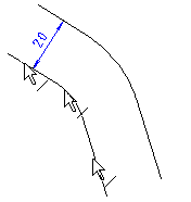
The Offset Line function can be used to copy a polyline selected from the sketch at the desired distance.
The Trim Lines function can be used to combine two straight line elements at their intersection point by continuing and/or shortening the lines.
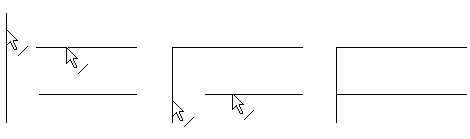
Trim Two Lines Together in a Sketch
Trim a Line to Another Line in a Sketch
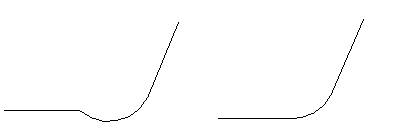
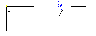
The Round function can be used to round a corner formed by two straight lines.
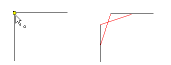
The Bevel function can be used to add a bevel to a corner formed by two straight lines. You can choose between two options when drawing a bevel.
The edit functions can be used to add or delete geometric constraints when editing elements. You should leave the determination of the constraints to as late as possible in the sketching.
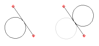
Mirroring an Element
Mirroring will copy the selected elements around the symmetry axis.
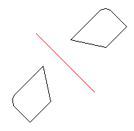
Mirror the Geometry of a Sketch
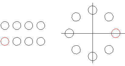
Creating a Line Pattern
When creating a line pattern, the lines selected from a sketch are copied in a straight or circular pattern. You must define the number and spacing of the elements to be copied in the line pattern. When creating a circular line pattern, you need to define the angle between the elements to be copied.