
Editing Project Parameters: Wall Framing Parameters
Framer
In the project parameters, you can define default values for wall frame such as the default lengths for wall panels, the default corner details, the default starting point of stud positioning, etc. Edit the wall framing parameters as follows:
- Open the project's document browser.
- Right-click
 Settings.
 - Select Edit Project Parameters.
The Project Parameters dialog box opens.
- At the top left corner, select the parameter set Wall Framing Parameters.
- Edit the parameters.
 Project Parameters Dialog Box
The wall framing parameters are customer-specific. Examples of possible wall framing parameters are presented here. The parameters of different wall types (bearing exterior wall, non-bearing exterior wall, bearing interior wall and non-bearing interior wall) are separated on tabs of their own in the dialog box. Each tab contains the same parameters.
Normally, you can only select certain predefined values for the parameters. Select the values from the lists. You can select various details in a selection drawing, which opens in the preview window. Select a detail by clicking a hot spot in the selection drawing. The label of the selected detail is displayed in the Value column.
Details
| Corner Details | Detail of a rectangular corner. Select by clicking a hot spot in a selection window. |
| Backers | Detail of a T intersection joint between walls. Select by clicking a hot spot in a selection window. |
| Angled corners | Detail of an angled corner. Select by clicking a hot spot in a selection window. |
| Plate break | Section detail of the top plate. Select by clicking a hot spot in a selection window. |
Panels
| Min. length | The minimum length of a wall panel. Select from the list or type the desired value. |
| Max. length | The maximum length of a wall panel. Select from the list or type the desired value. |
| Default length | The default length of a wall panel. Select from the list or type the desired value. If the field contains only one value, the program tries to cut the panels according to the default length. When the value is great enough, the panel length is always the same as the entire wall length. If a group of values forms the default length (for example 6000 4200 3600 3000 2400), the order of the values defines the most preferred panel length. The first value is used as panel length whenever possible. If the value is not suitable, the program selects the next possible value. Enter the values of the group separated by a space. |
Studs
| From | The default starting point of positioning studs. Select the Right, Left, Center or Left/Right radio button. The right and left of the wall are determined by the viewing direction. The starting point defined in the parameters of the frame layer overrides the default starting point defined in the project parameters. If Set Stud Rule According to Panelization has been selected in the wall panel settings, it overrides the starting point defined in the parameters of the frame layer. |
| Spacing | The default spacing of the studs. Select from the list. |
| Center Stud | You can select either single or double stud as the center stud of a panel. Select the number of studs from the list. |
| 1. stud | The default distance from the frame end to the center of the first stud. Type the value in the text field. |
| Number of Studs | Select single or double studs. |
Bottom plate
| Number | Number of bottom plate sections. Select from the list. |
| Width | The width of the bottom plate. Select from the list. |
| Type | Type of the bottom plate. Select by clicking a hot spot in a selection window. |
Top plate
| Number | Number of top plate sections. Select from the list. |
| Width | The width of the top plate. Select from the list. |
| Type | Type of the top plate. Select by clicking a hot spot in a selection window. If you select an option with beams, also select the width and height of the beam. |
| Beam width | The width of the beam of a top plate type with a beam. Select from the list. |
| Beam height | The height of the beam of a top plate type with a beam. Select from the list. |
Horizontal supports
| Height | |
| Type | 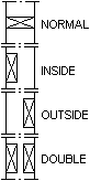 |
| Nailer height (interior) | |
| Nailer height (exterior) |
Opening properties
| Opening 1 | |
| Detail | Detail of window and door openings. Select by clicking a hot spot in a selection window. |
| Max width | The maximum width of the opening using the Opening 1 detail. Select from the list. If the opening is wider, use the Opening 2 detail. |
| Width | The width of the beam used in the opening detail. Select from the list. |
| Height | The height of the beam used in the opening detail. Select from the list. |
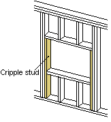
| Cripple stud | Number of support studs for the opening. Select from the list.
|
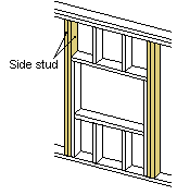
| Side stud | The number of king studs for the opening. Select from the list.
|
| Opening 2 | Like Opening 1. The Opening 2 detail is used, when the width of the opening exceeds the maximum width of Opening 1. |
| Opening 3 | Like Opening 1. The Opening 3 detail is used, when the width of the opening exceeds the maximum width of Opening 2. |
Misc
| Additional tolerance of an opening's bottom auxiliary frame | Defines the distance between the pieces below the opening and the opening. By using the additional tolerance, the opening can be enlarged without changing the size defined in the opening properties. |
| Additional tolerance of an opening's side studs | Defines the distance between the pieces at the edges of the opening and the opening. By using the additional tolerance, the opening can be enlarged without changing the size defined in the opening properties. |
| Additional tolerance of an opening's top auxiliary frame | Defines the distance between the pieces above the opening and the opening. By using the additional tolerance, the opening can be enlarged without changing the size defined in the opening properties. |