
Sheet Splitting
Sheet-Metal Design
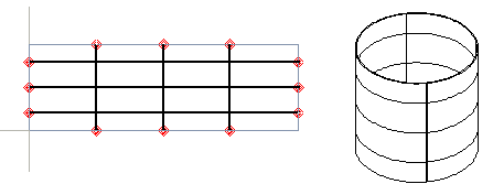
The split line feature can be used to create sheet splitting for a sheet metal part.
For example, using sheet splitting, you can model things like a tank built from several sheet blanks as a single model. The sheet seams are displayed for positioning through holes.
The advantage of this method compared to creating actual welding grooves, for example by a cutout extrusion, is that the model can still be bent and flattened even after the faces have been divided, both during modeling and for the model drawing.
Create sheet splitting during modeling when the model is flattened as follows:
- Add a new sketch to the face of the part.
- Draw a sketch, and select
 OK.
OK. - Select

 Split Line as the operation.
 - Select the surfaces that you want to split with the line in the Selected Elements 1 section. You can select all surfaces by selecting the context-sensitive function
 All in the list.
 - Select OK.
- Rebend the model back into a 3D model.