Extrude Thin Feature
Sheet-Metal Design
You can extrude a sketch as a thin feature. The sketch is extruded perpendicularly so that the sketch is either the sheet's inner or outer edge. If the first function of a part model is a thin feature extrusion, Sheet Metal is set as the part's type, after which you can select sheet metal design functions.
Note:
- Draw the sketch as a continuous line chain, for example with the
 Polyline function, so that you can select extrusion as a thin feature.
 - We recommend that you draw the sketch without rounding the corners. Add the bends to the sharp corners of a sheet in the dialog box Extrusion Data: Thin Feature. The program adds a separate Bend Radius feature on the sheet’s feature tree. You can add a bending radius also as a separate feature. Add Bend Radius
Extrude a sketch as a thin feature as follows:
- Add a New Sketch or edit an existing sketch.
- Sketch the shape to be extruded.
- Select
 OK.
OK. - Select

 Extrude.
 - Select
 Thin Feature.
 - Define the thin feature properties. Enter at least the length of the extrusion and the thickness of the sheet.
- Select OK.
Note:
- You can define a part modeled by an extrusion feature as a sheet-metal part by selecting it, clicking
 Properties and selecting Sheet-Metal as the part type. This is reasonable only when the part in question is a sheet-like volume.
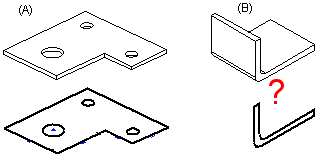
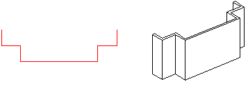
 - The picture includes the sketches and the parts (A) and (B) created with the Extruded Boss function. The cross section sketch of part (B) must be drawn so that the sheet will be of an even thickness. In the (B) case, roundings added to the sketch may cause problems in flattening.