
Add a Profile Freely to the Model Space
Profile Structure Design
General
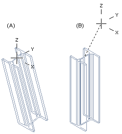
The cross-section of the profile is swept between freely selected points as a profile.
- After selecting the first point, the direction of the profile sweep must be entered.
- The default sweep direction of the profile is vertical, i.e. the Z axis direction of the assembly model.
- You can select the sweep direction
 or sweep plane
  before clicking the end point.
A profile part created this way
- Is a part fixed in place. If you want to use the constraints to fix it in place, you must first detach the profile and then remove the coincidence constraint from the 3d sketch of the profile.
- Contains a 3d sketch line that has a coincidence constraint to the plane selected as the starting surface.
- This coincidence constraint does not appear among the assembly constraints.
- The coincidence constraint is displayed if the context-sensitive function is selected for the selected profile: Edit Profile > 3D Sketch.
Differences between Vertex G4 and Vertex G4 Plant
 Vertex G4 Mechanical: Positioning freely placed profile parts using geometric constraints is an unwieldy and unstable method of modeling profile structures.
- We recommend a method whereby the profile part is modeled utilizing a jig formed from a guide curve.
- With the jig (skeleton), the shape and dimensions of the structure can be easily modified, and the geometry of the profile parts follows the changes of the jig.
Vertex G4 Plant: A freely added profile part remains in place, and it does not rotate in the model.- Geometric constraints are not formed between the profiles.
- If you use the Alt key when adding a profile, constraints are formed.
Add a Profile Freely to the Model Space
- Start adding a profile:
- Vertex G4: On the
 tab, in the Add group, select
  Add Profile.
 - Vertex G4 Plant: On the
 tab, in the Steel Structures group, select Add Profile.
 - Select the contextual function:
 Add > Profile
- Vertex G4: On the
- Select a profile cross section from the browser:
- By using the context-sensitive function
 Select or
 - By double-clicking the cross-section.
- Click the profile, drag it a little and release the mouse selection button.
- By using the context-sensitive function
- Select the table ID determining the profile size from the list.
- Or if the profile does not have a dimension table, enter the dimension in the dimension table that opens
- If necessary, attach item data to the profile part.
- Select a location for the cross section (starting point)
- Position the first profile part to be added as the first part to the model in the origin by clicking the middle mouse button.
- Define the sweep direction of the profile as one of the following or go to step 7
- Press U key or select the context-sensitive function : Constraint >
 X axis
 - Press the I key or select the context-sensitive function Constraint >
 Y axis
 - Press the O key or select the context-sensitive function Constraint >
 Z axis
- Press U key or select the context-sensitive function : Constraint >
- Instead of sweep direction, you can define the profile’s sweep plane to the main planes XY, XZ, and YZ.
- Press Shift+U or select the context-sensitive function Constraint >
 Horizontal (XY) Plane.
 - Press Shift+I or select the context-sensitive function Constraint >
 Vertical (XZ) Plane.
 - Press Shift+O or select the context-sensitive function Constraint >
 Lateral (YZ) Plane.
- Press Shift+U or select the context-sensitive function Constraint >
- Define the profile length:
- Enter a value on the keyboard or
- Select an end point from the model space.
- Add the next profile. If you want to change the profile you want to add:
- Click the middle mouse button or
- Press the V key. (V= Confirm).
- Select the context-sensitive function:
 OK.
OK. - Select a new profile, etc.
- When you want to stop adding profiles:
- Select another function or
- Press the Esc key.
Note:
- You can change the length of a profile added in this way by editing the 3D sketch of the profile.
- If you do not define the position of a profile part accurately when modeling it, you need to position it in the assembly using geometric constraints. If necessary, you can fix it in place.