
Layer Parameters of a Floor or Ceiling
Layer parameters are available for selection, when you have selected a layer in the Layers list or in the preview image. If you have selected a particular floor or ceiling volume in a model and opened its properties for editing, you can only edit the properties and parameters of the volume in question. You cannot select other layers.

By default, only some parameters are displayed in the dialog box. You can display more parameters as follows:
- Open the context-sensitive menu in the parameter list.
- Select Show All Parameters.
Basic Parameters
You can select the following general parameters for a layer:
-
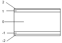
Order number - The order number of the basic layer of the structure is 0. The order number of the basic layer of the structure is 0. The layers below the basic layer are numbered with negative numbers starting from one, and the layers above the basic layer respectively with positive numbers, for example:
-
 Part of core layer when layers are packed - The presentation method of a floor or a ceiling in the model can be either layers expanded or a packed basic volume. The packed basic volume consists of layers which have this property. The thickness of the basic volume is the same as the total thickness of the layers forming it. You can change the presentation method of a floor or ceiling in the model from the packed basic volume to a detailed presentation by expanding the layers.
 -
Display in 2D - Select the edge line of the layer to be visible in the floor plan.
-
Align layer edges with core layer - Define the edge of the layer to follow the edge of the basic volume when the layers are expanded in the model. This property is significant, for example, in roof structures. The layers above the basic volume conform to the selected eave shape when their edges have been defined to follow the edge of the basic volume.
-
Horizontal overlap - Defines the horizontal edges of the layer to extend beyond the edges of the basic volume. Type the value in the field. You can view the overlaps in the model when you expand the layers.
-
Vertical overlap - Defines the ascending edges of the layer, for example the ends of a gable roof slope, to extend beyond the edges of the basic volume. Type the value in the field. You can view the overlaps in the model when you expand the layers.
Surface properties
Select a category which defines the layer's surface material to be displayed in the model. The default category for each layer is defined in the layer library. The surface material of the category is defined in the rendering material library. You can select different categories for both coarse and accurate models.
-
Surface (coarse) - The material will be displayed in the building model when the configuration of the structure is coarse.
-
Surface (accurate) - The material will be displayed in the building model when the configuration of the structure is accurate.
In the accurate model, you can apply a texture on the surface of the layer. The texture is displayed in the model after you have selected the accurate presentation for the structure with the Presentation > Accurate function, and, in addition, you have expanded the layers with the context-sensitive function  Expand Layers.
- Texture file - Can be either a drawing or a model file.
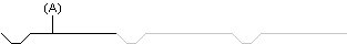
- Drawing - You can texture the surface of a layer with a 2D hatch. Enter the name of the drawing file in the field. If you are using the hatch included in the basic software delivery, the name of the drawing file is panel120.vxp. It has been saved in the ../system/macros/areas folder. You can also draw the basic hatch shape yourself, and save it as a drawing file (*.vxp) in the ../custom/macros/areas folder. The program will generate a machining polyline by copying the basic shape (A) repeatedly.
- Model - You can define an accurate presentation method for the cover layer of a roof by using a model file. Enter the name of the model file in the field. The model files included in the basic software delivery are saved in the ../system/macros/areas folder:
- corrugated.vxm - Corrugated sheet
- kolmiorima.vxm - Corrugated sheet for a felt roof
- mach_seamed.vxm - Machine seamed sheet metal
- ormax.vxm - Tile roofing
- Drawing - You can texture the surface of a layer with a 2D hatch. Enter the name of the drawing file in the field. If you are using the hatch included in the basic software delivery, the name of the drawing file is panel120.vxp. It has been saved in the ../system/macros/areas folder. You can also draw the basic hatch shape yourself, and save it as a drawing file (*.vxp) in the ../custom/macros/areas folder. The program will generate a machining polyline by copying the basic shape (A) repeatedly.
- On top surface - Select the top surface of the layer to be textured. When the property is not selected
 , the bottom surface will be textured.
 - Angle - Defines the direction of the texture. Enter the desired value in the text field. The angle is defined in relation to the x axis.
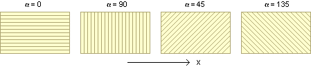
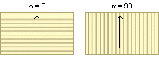
On a slope the angle is defined in relation to the horizontal edge. In the figure below, the arrow points the direction of the slope.
- Usable Width - Defines the rise of a single board in a cladding. The usable width is intended to be used together with the texture angle when the texture file is parametric, in other words when the width of the board is controlled with a dimension constraint. The value of the usable width is loaded as the value of the dimension constraint. This enables claddings of varying widths by using just one texture file. Solving the constraints requires that 2D Constraint Manager is enabled. The default value of the effective width is set in the layer library.
- Hatch as lines, to enable snapping to them - When this property is selected, the hatch of the layer is exploded to lines. This enables you to snap to the line points.
 If the hatch is dense, a lot of lines are created. This may make the model slower to handle.
Other Parameters
- Hatch - You can add a hatch to the layer by enabling the property. Select a pre-made property set for the hatch from the list, or define the Type, Layer, Pen, Scale, and Color properties individually.
-
3D Line Properties - Select a pre-made property set for the line from the list, or define the Line type, Layer, Pen, Scale, and Color properties individually.
-
2D Line Properties - Select a pre-made property set for the line from the list, or define the Line type, Layer, Pen, Scale, and Color properties individually.
-
Section hatch - Defines the layer's cross section hatch which will be added in the vertical cross section created from the building's 3D model. Select a pre-made property set from the list, or define the Type, Layer, Pen, Scale, and Color properties individually.
 Note
Note
- The default values for the layer parameters have been defined in the layer library.