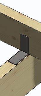
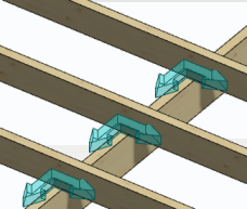
Beam to Beam
Form a connection between the primary beam and another beam. When you move either beam, the connectors move with it.
- Select Modeling | Connection |
 Joint >
  Connection Details.
 - Select the Beams folder in the browser.
- Double-click Beam to beam. A dialog box will open where you can select connection properties.
- Select one of the following as the connector library:
CLEAT_SYS 
CLEAT_CUS 
CLEAT_CULLEN 
CLEAT_SIMPSON 
- To select the connector, click the Sel button. The button opens a list in accordance with the library selected, from which you can select the connector.
- Select either of the following:
- One Side - The connector is only added on one side of the beam to be joined.
- Both Sides - The connector is added on both sides of the beam.
- Confirm the connection properties and close the dialog box by clicking OK.
- Select the primary beam.
- Select the beam to be connected to the primary beam. Select several beams with the Ctrl key pressed down.
- Select Confirm. The program will mark the connections with arrow symbols.
- If necessary, mirror or rotate the symbols before accepting the connections. Right-click to open the auxiliary function menu and select one of the following:
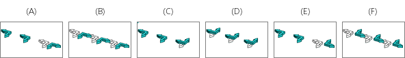
 Mirror - Click the symbol to be mirrored (A).
 Mirror all - All symbols are automatically mirrored (B).
 Mirror - Click the symbol to be mirrored (C).
 Mirror all - All symbols are automatically mirrored (D).
 Rotate - Click the symbol to be rotated (E).
 Rotate all - All symbols are rotated automatically (F).
When you mirror or rotate a single symbol, the selected auxiliary function is enabled until you select another auxiliary function. If necessary, click the symbol again until the desired position is reached. When you mirror or rotate all the symbols, you can mirror or rotate all again by reselecting the function from the auxiliary menu.
- Select Confirm.
- If necessary, delete the existing connection by selecting Delete in a message box.
The program will position the connectors on the center line of the primary beam. If the beam to be connected does not reach the center of the primary beam, the connection will not be formed. The geometry of the connectors is displayed both in the 3D model and the 2D drawing.