Select Tool from the list. If necessary, edit the tool parameters in the dialog box. The parameters define the details, cross sections of parts, spacing and other necessary values to be used. The default values for the parameters are read from the project parameters. Parameters are customer-specific. Some basic parameters are described in this guide.
The thickness of the frame layer is determined according to the widest cross section (stud/top plate/bottom plate). The thickness of a layer changes according to the selected cross section. The thickness only changes in the structure model, not in the architectural model.
Frame: Gen
- Framing Detail
- Select from the list.
- Framing Name
- The name of the tool. Presented in the Tool list.
- Panel Label
- The first part of the wall panel label.
- Ext. Corner Type, Int. Corner Type, Backer
- Details of a rectangular corner and backers. Click the Sel button, and select a detail from a drawing window by clicking the hot spot. The detail of an angled corner is defined in the project parameters.
- Stud Spacing
- The distance between the studs of a wall panel, measured from center to center. Select the value from the list, or type a value in the text field.
-
Note: The sheathing tool property Sheet Generates Studs overrides the stud positioning in the frame layer parameters. The studs are positioned according to the sheet seams.
- Stud Start From
- The starting point of the studding of a wall panel. Select one of the following:
- Right - Starting from the right edge according to the stud spacing.
- Left - Starting from the left edge according to the stud spacing.
- Center - Starting from the center to both directions according to the stud spacing.
- Left/Right - Starting from both edges to the center according to the stud spacing.
- Free - Studs are placed on the panel at an even spacing, with the spacing smaller or equal to the Stud Spacing.
- The right and left of the wall are determined by the viewing direction. The viewing direction is selected in the wall panel settings when generating the panel breaks.
- Center Stud
- The center stud of a wall panel can be either a single or a double stud. Select the radio button Single or Double.
- Insulation
- Select this checkbox, when you want to add insulation to a frame layer. Please note to also select the insulation from the insulation library by clicking the Select button. If the value in the field is NO, insulation will not be added.
- Cutting of insulation is affected by the keywords in the system settings:
- ins_max_edge_offsets
For example, ins_max_edge_offsets= 20 20.
Defines the maximum offset for the edge of the insulation. The edge of the insulation is moved to the edge of the nearest stud, if the distance is the given value at the most. The first value is for the outer edge, and the second for the opening edges.
- ins_cutting_pcetypes
For example, ins_cutting_pcetypes= 1.
Defines the profile types which will fully cut the insulation, even though the profile would be thinner than the insulation. You can enter several values separated by a space or comma. Type 1 is bottom plate.
- If the frame consists of I-beam structures, select whether to add the insulation to the profile web or not:
- No - The insulation will be added according to the profile's rectangular cross section.
- Yes - The insulation will be added according to the I-beam cross section.
- An insulation can be defined as Injected in the insulation library. The injected insulation is cut in the structure with the surrounding parts, whereby the insulation has a precise shape. The insulation is a part model which cannot be edited by using the grip points. You can define the property by editing the insulation library:
- Select System | Structural Libraries |
 Sheathing >
  Insulation.
- Move to the row of the insulation or add a new insulation.
- Select x in the Injected field.
- Under Trusses
- Always add a frame stud at the location of a truss above the wall. If an opening is at the truss location, a stud is added only above the opening. If the truss spacing is greater than stud spacing, the other studs are added according to the selected stud rule.
- In the example figure, Stud Start From is Free, in which case other studs are placed at an even spacing between the trusses.
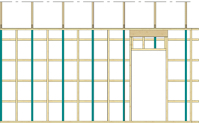
- If some other stud rule is selected, the studs will be placed according to the first truss.
Frame, Plate, Blocks
- Top Type
- Click the Sel button, and select a detail from a drawing window by clicking the hot spot. If necessary, select a dimension connected to the detail from the Dimension list, or type a value in the text field.

- Top Plate
- Select the cross section from the profile library by clicking the Sel button.
- Piece Properties
- If you select an option with a beam, also select the Beam along Top Pl. cross section from the profile library by clicking the Sel button.
- Head Binder
- Select the cross section from the profile library by clicking the Sel button.
- Piece Properties
- Bot. Type
- Click the Sel button, and select a detail from a drawing window by clicking the hot spot. If necessary, select a dimension connected to the detail from the Dimension list, or type a value in the text field.

- Bottom Plate
- Select the cross section from the profile library by clicking the Sel button.
- Piece Properties
- If you select an option with a beam, also select the Beam along Bottom Pl. cross section from the profile library by clicking the Sel button.
- Stud
- Select the cross section from the profile library by clicking the Sel button.
- Piece Properties
- Select single or double studs by selecting an option from the No list.
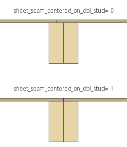
Note: When double studs are selected, you can control the position of the sheet seam in the system settings with the keyword sheet_seam_centered_on_dbl_stud.
- sheet_seam_centered_on_dbl_stud= 0 - The sheet seam is located in the middle of the other stud. Default value.
- sheet_seam_centered_on_dbl_stud= 1 - The sheet seam is located in the middle of the double stud.
- Block
- Select blocking by selecting the check box Horiz. (A) or End (B), or both.
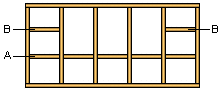
- Select the cross section of the blocking by clicking the Sel button. Select the position height of the blocking from the Height list, or type the height in relation to the floor base height in the text field.
- Select the Type of the blocking from the list:
- Blocking is trimmed to adjacent parts. Trimming of short blocking can be controlled in the system settings with the keyword stretch_short_blockings.
Frame, Openings
- Header 1, 2, 3
- The use of the details is determined as follows:
- Detail Header 1 is used when the width of the opening is smaller than or equal to the value in the Max field on the same row.
- When the width of the opening exceeds the maximum width of Header 1, detail Header 2 is used.
- When the width of the opening exceeds the maximum width of Header 2, detail Header 3 is used.
- Click the Sel button, and select a detail from a drawing window by clicking the hot spot.
- Select the cross section of the beam to be used in the opening details from the profile library by clicking the Sel button.
- Piece Properties
- Select the maximum width of the opening from the Max list.
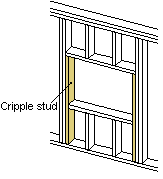
- Cripple Stud
- Select the cross section of the cripple stud from the profile library by clicking the Sel button. Select the number of the cripple studs from the list.
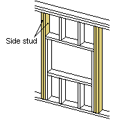
- Side Stud
- Select the cross section of the side stud from the profile library by clicking the Sel button. Select the number of the side studs from the list.
-
Note: In a situation where the frame stud and opening side stud of a wall panel overlap, you can control the adding of the studs in the system settings with the keyword adjust_studs_to_studs.
- adjust_studs_to_studs= 0 - The frame stud is not added at all. This can result in a larger space between studs next to the opening.
- adjust_studs_to_studs= 1 - The frame stud is moved next to the side stud.
