
Framing Tools: Frame - Wall Sub Frame
Framer
Tool for a wall panel's sub frame layer (FRAME, FRAMING). Select Tool from the list. If necessary, edit the tool parameters in the dialog box. The parameters define the cross sections, spacing, and other necessary values of the parts.
The thickness of a layer changes according to the selected cross section. The thickness only changes in the structure model, not in the architectural model.
Frame: Gen
- Spacing
- Select the part spacing from the list or type the desired value in the text field.
- Cross sections
- Select the cross sections for the sub frame parts. If a cross section field is empty, a part will not be added.
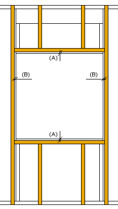
- Opening Offsets
- Defines the distance of the pieces to be placed at the edges of the opening from the edges of the opening. Enter the values in the Top/Bottom (A) and Left/Right (B) fields.
- Insulation
- Select this checkbox, when you want to add insulation to a sub frame layer. Select the insulation from the insulation library with the Select button. The default thickness of insulation is the thickness of the layer.
Direction and Alignment
- Flip
- Defines the rotation angle by which the direction of the sub frame will be rotated in relation to the main frame layer. Select 0, 90, 180 or 270 from the list.
- Align
- Defines how the parts are to be spaced. Select from the list:
- Offset
- Defines an additional offset, when you select the Left or Right option for aligning. A positive value moves towards the frame area, a negative value away from the area.