
Model a Truss on a Work Plane
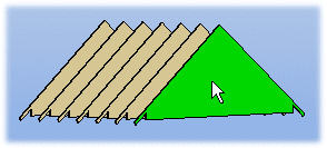
The shape of the truss you are modeling is created by adding a truss area to the roof. The program also adds truss volumes. The volumes only contain a shape, not the parts. Model the truss on a work plane to attach the profiles to the truss. If the shape of the roof changes and you update the shape of the truss, the truss parts will be adjusted accordingly. However, the basic shape of the truss should remain the same. Add profiles and attach the profiles to a truss volume and to each other using geometric constraints and profile joints.
- Activate the model window.
- Select Modeling | Connection |
 Distance
 Activate New
Workplane.
Activate New
Workplane. - Select a truss volume.
- Select Confirm.
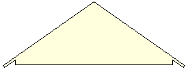
- Rotate the model until the volume is perpendicular. For example, select
 Select From
Model from the tool strip, and select the truss volume.
Select From
Model from the tool strip, and select the truss volume.
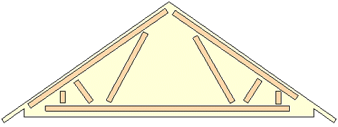
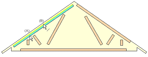
- Add the profiles in approximately their correct positions. Please note that the locating
point is set on the work plane.
- The program automatically attaches the bottom chord to the nearest height level. To attach
the bottom chord to the bottom of the truss volume, delete the height constraint as follows:
- Select the bottom chord.
- Right-click to open the context-sensitive menu.
- Select 3D Levels.
- Select an empty option from the Locating height list.
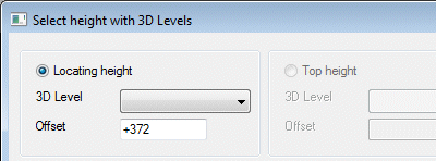
- Confirm by clicking OK.
- Select the bottom chord.
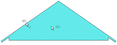
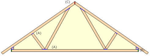
- Attach the top and bottom chords and the outermost bars to the edges of the truss volume
using coincidence constraints. Select the profile (A) and the profile line (B), then select
the truss volume (C) and the truss volume line (D).
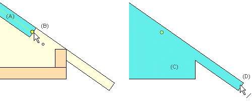
- Attach the ends of the upper chords to the truss volume using coincidence constraints.
Select the profile (A) and the end line of the profile center line (B), then select the
truss volume (C) and the truss volume line (D).
- Attach the profiles to each other using profile joints. Use, for example, the following joints:
- Modeling | Connection |
 Joint Profiles
 Front -
Connect the ends of the bars to the bottom and top chords (A).
Front -
Connect the ends of the bars to the bottom and top chords (A). - Modeling | Connection | Joint Profiles
 Back -
Connect the end of the bottom chord to the outermost bar (B).
Back -
Connect the end of the bottom chord to the outermost bar (B). - Modeling | Connection | Joint Profiles
 Exterior
Corner - Connect the ends of the top chords using a miter joint (C).
Exterior
Corner - Connect the ends of the top chords using a miter joint (C).
- Modeling | Connection |
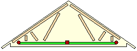
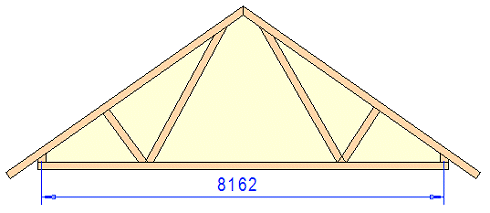
- Add distance constraints. First add a distance constraint that defines the length of the truss.
- This dimension is not added as a driving dimension parameter (the length does not change), so the Drives geometry checkbox should be cleared.
- You can define a dimension as a variable using the Formula button. Type, for example, #L in the Formula field.
- In the example figure, the dimension constraint has been added between the center lines of the outermost bars.
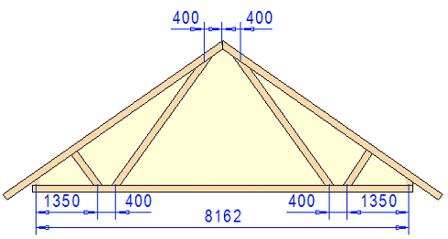
- After that, you can add dimension constraints between parts.
- Select the check box Drives geometry because dimensions function as driving dimensions.
- Always add a dimension constraint according to the center line of a part.
- Assign a value to the dimension or use the length variable defined above. Type, for example, #L/6 in the Formula field.
- After finishing the truss, close the work plane. Select Modeling |
Connection | Distance
 Close Workplane.
Dimension constraints are no longer displayed in the model.
Save the finished truss to the library.
