
Adding Constraints in a Model
To specify the position of the building components in relation to each other, you can add constraints to determine and dimension the relationship between the components.
 You can prevent the adding and solving of constraints in the model by disabling the constraint manager.

Constraint Types
You can add constraints between the components to determine the position of the components in relation to each other. Constraints are defined between the elements of two components. An element can be a face, line or point. Constraints defined for the components include, for example, distance and angle dimensions. These driving dimensions can be used to control the direction and position of the components in relation to each other.
The following geometric constraints can be determined for the building components:
Please note that in order to position a single component correctly and in the correct direction in relation to the other components, you may need to define more than one constraint for the component.
You can add geometric constraints by selecting a constraint from the Modeling | Connection |  Distance menu.
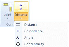
First, select a function, and then the components and elements between which you wish to add the constraint.
Undoing, Viewing, Editing and Deleting Constraints
You can undo the constraint last added by pressing Ctrl+Z before exiting constraint definition. The previous constraint solution is not restored.
You can view, edit and delete the constraints by selecting a component and the context-sensitive menu function  Constraints. An unresolved constraint can be disabled and again enabled.