Example: Add an Interior Wall with a Wood Frame and Panel Siding
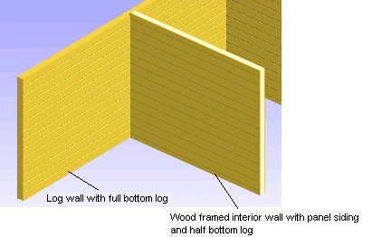
In this example, an interior wall is added to a 2D drawing. The interior wall's direction is perpendicular to a log wall with a full-height bottom log. Select half a panel as the height of the lowest panel of the interior wall siding.
- Activate the 2D drawing window.
- Select Modeling | Wall Layout |
 Wall.
Wall. - Select wood frame and log panel siding as the wall structure.
- Select the
 Log panel wall auxiliary function.
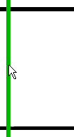
 - Select the log wall with a cursor.

- Select Confirm.
- Select the height of the bottom panel. Select the Half radio button in the dialog box.
- Select
 Wall middle as the locating point.
 - Add an open wall chain. If the
 Toggle open/closed wall button is not selected, you will add an open wall chain. If the button is selected, you will add a closed wall chain.
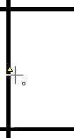
 - Select the start point of the wall.

In the example, the center point of the line depicting the interior surface of the log wall is selected.
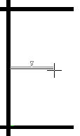
- Lock the cursor in the direction of the X axis in one of the following ways:
- Press the U key.
- Move the cursor in the direction of the X axis until the cursor looks like this
 and click the left mouse button.
 - Select Constraint > X axis from the context-sensitive menu.
- Type the distance from the start point to the end point. Type the distance in the Distance field of the Coordinates Input dialog box. The dialog box will open when you press a numeric key on the keyboard.

- Select Confirm.
- Exit the function by pressing Esc.
- Activate the 3D model by pressing F2.

