
Log Wall Parameters
Define the structure of the log wall to be added by setting the wall parameters in the dialog box.
Tab: Wall parameters
Select the log wall parameters on the first tab of the dialog box.
- Log profile
- Select the log profile from the list. The list consists of the cross sections in the LOG profile library. The profile label usually indicates the log type (planed or round) that has been defined for the cross section. Either of the radio buttons Planed log or Round log is automatically updated according to the log type of the selected profile.
- Log wall / Log beam
- Define how the wall to be added is connected to the crossing wall by selecting one of the following radio buttons:
- Wall base height
- Type the height of the bottom of the log wall in relation to the floor base height. The height of the bottom of the log wall = the height of the lowest point of the bottom log. The default height position is read from the project parameters.
- Siding Top Height
- Type the height of the log wall. You can type the height either in millimeters or multiples of log courses, for example 15H, where H = height of one log course. The height of a log wall is the distance between the lowest point of the bottom log and the highest point of the top log. The default height is read from the project parameters.
- No depression
- If a log wall has the parameter No depression, the program does not suggest adding a settling space when you add a log column.
- Top log
- Select either of the following as the type of the top log:
Tab: Profile parameters
The parameters of the selected log profile are displayed on the second tab of the dialog box. The parameters are read from the LOG profile library. You can change the values of only the Crib width, Height of bottom log and Height of half log parameters.
- Log profile
- You can reselect a log profile from the list. The list consists of the cross sections in the LOG profile library.
- Log width
- The width of the selected log profile.
- Log height
- The height of the selected log profile.
- Log net height
- The net height of the selected log profile.
- Notch width
- The width of the crib is, by default, the same as the width of the log. If necessary, you can type a value for the crib width that is smaller or than larger than the log width. When the field is empty, the default value is used.
- Base log height
- The height of the bottom log of the wall may be smaller than the normal height of the log profile (the Log height parameter). Type the height in the text field. The parameter is the same as the Full parameter in the wall height data and the log profile library.
- Half log height
- The bottom log of a wall may be a half log. Type the height of a half log in the text field.
 When defining the height of the
bottom half log, take into consideration how you want the risers of crossing walls to be
positioned in relation to each other. If, for example, you want the riser of the bottom
half log to be half of the riser of the bottom full log, the height of the bottom half log
will then be
When defining the height of the
bottom half log, take into consideration how you want the risers of crossing walls to be
positioned in relation to each other. If, for example, you want the riser of the bottom
half log to be half of the riser of the bottom full log, the height of the bottom half log
will then be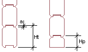
- Lumber width
- The width of the log billet.
- Lumber height
- The height of the log billet.
Tab Corners
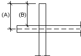
- Corner length
- The default corner length is the one defined in the profile library. If necessary, type a new length in the field. Select a line for the wall from which the corner overlap will be measured:
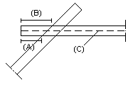
- Corner mode
- Select the edge that determines the corner overlap in an oblique corner. The default edge is the one defined in the profile library. Select one of the following as the measuring method:
 Note
Note
- You can open the log wall parameters for re-editing while adding the wall with the Select Another Wall function in the auxiliary menu.