
Add a Component to the Center Line of a Pipe/Duct
Piping Design
By default, a component will be positioned in the direction of the pipe's/duct's center line when you lock the component to a pipe/duct.
- Do either of the following:
- Select Modeling |
 Pipe
Pipe 
 Part.
Part. - Select Modeling | Pipe
 Part.
Part.
The browser is opened.
- Select Modeling |
- Select a component.
- Select properties for the component:
- Select properties in the fields on the tab.
- If editing the component in a dimension table is allowed, select the
Piping | Component |
 Dimensions, and edit the properties.
- Before locking the component to the pipe/duct center line, you can rotate the component using auxiliary functions.
- When adding a component in a model, use snap functions:
- Snap to line and point

- Snap to all geometry

- Snap to line and point
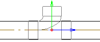
- Click the center line of a pipe/duct. The component is locked on the center line. You can still move the component along the pipe/duct.
- Before clicking a location for the component, you can rotate or mirror the component, or
change its locating point. If necessary, rotate the component in the model Activate the
model window by pressing the F2 key. Return to the drawing window by pressing the F2 key again.
- Rotate the component
 Rotate to the Left or Right by a Single
Rotation Step
Enter the Rotation Angle around the Z
Axis
Rotate to the Left or Right by a Single
Rotation Step
Enter the Rotation Angle around the Z
Axis - Mirror the component
If necessary, mirror the component before selecting its position. Click the button:

- Change the reference point
The default locating point is the component's grip point. If necessary, you can click a new point relative to which you position the component. Click the button:

- Rotate the component
- Indicate the component position on the center line of the pipe/duct.
 Note
Note
- You can also set the pipe component on the side of the pipe by pressing the Alt key and clicking the center line of the pipe in the model.