
Stair Type Parameters
Select the stair type from the list in the Stair type tab of the Stair Tool dialog box. The parameters you can select depend on the stair type.
- Basic Parameters
- Run line parameters
- Angle settings
- Flight settings
- Other Parameters
General parameters
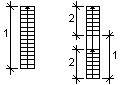
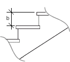
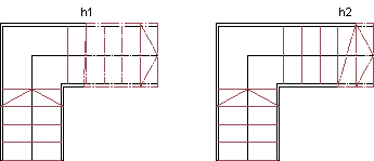
- Storey height - The default storey height (h) is loaded from the
project parameter Default Stairs Height (STAIRS_HEIGHT).

- Width - With this parameter, you can set the width of all flights
to be the same. After this, you can separately change the width of individual flights.
 The final stair dimensions depend on
the string type and string width.
The final stair dimensions depend on
the string type and string width. - Length 1, 2 3 - Flight lengths according to the stair type. The final stair dimensions depend on the
string type and string width.
- Straight Stairs
- L Stair
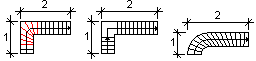
- U Stair
- Z Stair
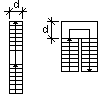
- Straight Stairs
- Landing depth - Landing depth (d). You can change the landing
dimensions in the angle settings.
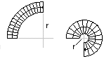
- Angle - Angle of curved stair (a).
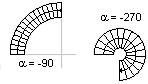
- Inner radius - Inner radius of curved stair (r).
Run line parameters
- 1./2./3. flight step count - Number of steps in an individual flight.
- Step count - The program calculates the total number of steps in all flights.
- Run (a)
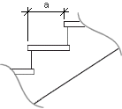
- Rise (b)
- 2x rise + run - The program calculates the dimensioning reference value. The limiting values can be defined in the system settings with the stair_design_limits keyword. Default is 600 - 650 mm.
Angle settings
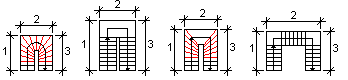
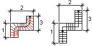
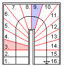
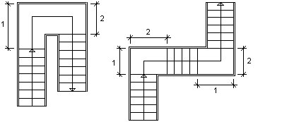
- 1. corner step - The first step of a corner that is not a
fixed-width straight step. Enter the serial number of the step in the text field. For
example, the stair below has two corners. The first corner step of the first corner is step
number 3, and the first corner step of the second corner is step number 9. In the preview
image, the corner steps are drawn in red.
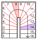
- Last corner step - The last step of a corner that is not a
fixed-width straight step. Enter the serial number of the step in the text field. For
example, the stair below has two corners. The last corner step of the first corner is step
number 8, and the last corner step of the second corner is step number 14. In the preview
image, the corner steps are drawn in red.
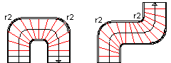
- Right side radius - The radius of curvature (r1) of the right
corner when going up the stair.
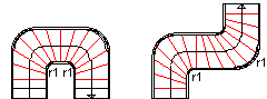
- Left side radius - The radius of curvature (r2) of the left corner
when going up the stair.
- Run line radius - The radius of curvature of the run line in the corner.
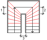
- Landing length 1, 2 - The landing dimensions in the corner.
- Landing right side depth - The inside dimension (3) of the landing
with the stair type UV landing stair.
Flight settings
- 1./2./3. flight width - The initial value is the same as the value of the parameter Width. If necessary, enter the new width in the text field.
Other parameters
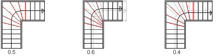
- Run line location - In spiral stairs, a run line is the line at
which the step run is a value according to the Run parameter. The
flight width is multiplied by the parameter in order to obtain the distance of the run line
from the edge of the stair. Changing the parameter influences the stair dimensions.
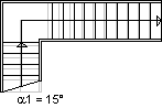
- Start angle - The angle (a1) of the front edge of the first step.
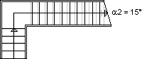
- End angle - The angle (a2) of the rear edge of the last step.
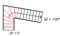
- 1./2./3. flight angle - The angle of the flight in relation to the
upright.
- 2D drawing layer - You can define the layer of the stair's 2D
geometry in two ways:
- All lines and texts are added on the same layer. Enter the layer number as the value of the 2D drawing layer parameter.
- The lines are added on the layers that are defined in the settings (default is layer
82). The texts are added on the layers that are defined in the step and stair tool
programs. In this case, enter -1 as the value of the 2D drawing
layer parameter (default).
 Line Properties in a 2D DrawingStep
and Stair Tool Programs
Line Properties in a 2D DrawingStep
and Stair Tool Programs
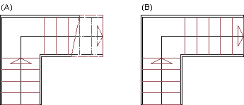
- Reflection is mirrored - This parameter has an effect only if the
cut line (A) has been selected to be visible in the stair's 2D geometry. By default, the
geometry of a reflected stair is not mirrored (B). If you wish to mirror the geometry of a
reflected stair, select Yes from the list. In this case, the lines
below the level defined by the cut line are drawn in reflected geometry according to the
properties defined in the settings (C).
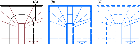
- Cutline visibility - Show (A) or hide (B) the cutline in the
stair's 2D geometry.
- Cutline location - The cutting height which determines the location
of the cutting line in the stair's 2D geometry.
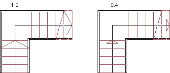
- Arrow size - The size of the arrow pointing the direction of the
stair in the stair's 2D geometry. May have the value 0..1. With value 1, the arrow is of the
width of the stair.
- Run line length - The program calculates the total run line length.
- Step tool program - The application development program which adds step numbers to the stair's 2D geometry. Several programs can be used for different stair types. The program must be located in the ../macros/triggers folder.
- Stair tool program - The application development program which adds stair data, such as rise, run, number of steps and landings, to the stair's 2D geometry. The program must be located in the ../macros/triggers folder.