Create a Pattern Along a Guide Curve
The pattern is guided along a curve or a tangential chain of lines. The pattern members can be set either at fixed intervals or evenly over the entire guide curve.
The instructions describe the creation of the pattern with the context-sensitive function:
- Select the part from which you wish to create a pattern from the assembly.
- Select the context-sensitive function
 Pattern.
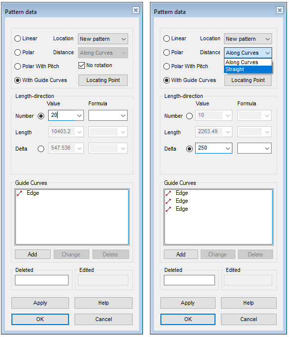
 - Select With guide curves in the dialog box of the assembly pattern.
- Click the lines that act as a guide curve.
- The lines must be tangential to each other.
- Select Confirm to stop clicking guide lines. (Confirm = V key, middle mouse button or the context-sensitive
 OK.
OK.- The program shows the length of the line chain in the Length field.
- If necessary, you can remove part of the guide curve from the Guide Curves list in the dialog box with the Delete button.
- If necessary, you can add a tangential line to the guide curve with the Add button.
- Enter the number of pattern members.
- The program shows the distance between the pattern members in the Delta field if they are set at equal intervals.
- Select
 Delta and enter the distance between the pattern members if you want the pattern members to be set at fixed intervals.
- If you selected Delta, you can select the Distance.
- If you selected
- Select the distance (only possible if you selected Delta).
- Along Curves (Default). In this case, the distance is calculated along the line.
- Straight. In this case, the distance is calculated directly as the distance between two points. See the figure below.
- If necessary, select
 No rotation.
 = The aim is to keep the direction of the parts in relation to the curve the same as it is in the part to be patterned.
- = The direction of the parts remains the same as in the part to be patterned.
- Select OK.
Distance calculation options
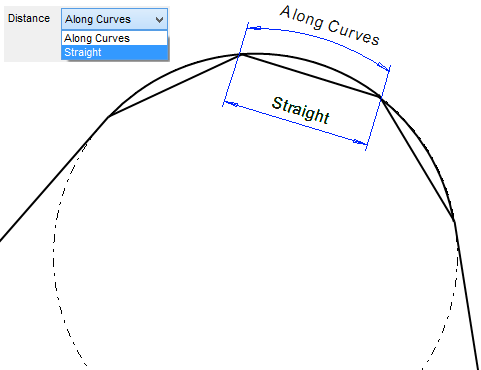
- Along Curves.
- Straight. Suitable for bicycle chains and electricity pylons, for example.
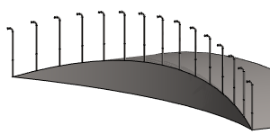
Example, the pattern members are set at equal intervals on the guide curve.
- Number 15 (Delta is not entered). Note that the pattern is set along the entire length of the line.
- Selected: No rotation.
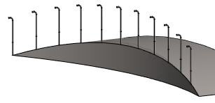
Example, the pattern members are set at fixed intervals on the guide curve.
- Number 11.
- Delta 950, Along Curves. Note that the pattern does not extend to the end of the line.
- Selected: No rotation.
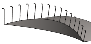
Example, the pattern members rotate according to the guide curve.
- Number 15 (no delta value). Note that the pattern is set along the entire length of the line.
- Not selected: No rotation.
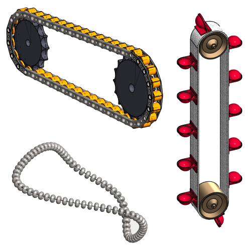
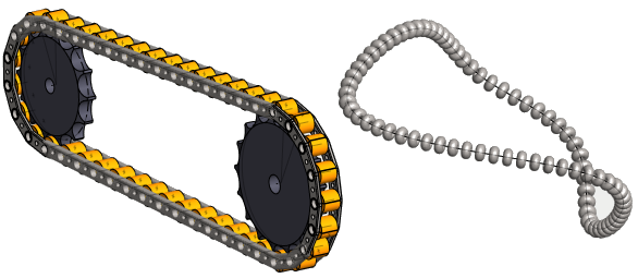
Other examples
- Chain: The guide curve consists of two arcs and two segments. The Delta dimension is entered with the distance parameter Straight.
- If the Delta dimension had been entered Along Curves, the chain would not be positioned correctly at the sprocket and the straight section, but only one of them could be in order.
- String of pearls: The guide curve consists of a closed spline curve added in the 3D sketch. The number of pearls is entered, so they are set at equal intervals on the line chain.
- Cup belt: The guide curve is projected onto the belt surface (2 curves and 2 segments). The number of cups is entered.