
Create a Polar Pattern in a Plane
Create a polar pattern in a circumferential shape or both circumferentially and lengthways.
The instructions describe the creation of the pattern with the context-sensitive function:
- Select the part from which you wish to create a pattern from the assembly.
- Select the Pattern function from the context-sensitive menu.
- Select Polar in the dialog box of the assembly pattern.
- Confirm the location New pattern.
- Select the direction: The direction only matters if the members of the pattern are not equally spaced on a full circle.
- Clockwise.
- Counterclockwise.
- Enter the number of pattern members in the Circle-direction.
- Enter either:
- The angle at which the pattern members are placed, or
- 360 = The members are placed at equal intervals on a full circle.
- Delta, or the angular spacing of two pattern members.
- The angle at which the pattern members are placed, or
- If you want to affect the diameter of the circle of the control part, enter the Radius of the circle.
- Note that this does not solve for the radius of the polar pattern.
- If you want the polar patterns to overlap, enter in Length-direction:
- The number of overlapping patterns in the Number field and
- The overlapping distance of the pattern members to the Delta field.
- Select OK.
- Click the position of the center point of the circular control part in the assembly.
- Note that the position of the center point of the guide curve part relative to the part to be patterned solves the radius of the polar pattern.
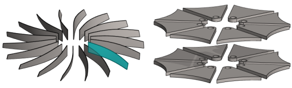
Example of a polar pattern
- Number in circle-direction 18, Angle 360.
- There is only 1 part in the length-direction (1= default value).

Example of a polar pattern, where there are also parts in the length-direction
- Number in circle-direction 7, Angle 180 (= equally placed on a semicircle).
- There are 3 parts in length-direction, delta 40.

Example of a clockwise and counterclockwise polar pattern
- Number in each pattern 5.
- Angle in each pattern 90.
- The pattern on the left is done clockwise and the pattern on the right is done counterclockwise.
Note:
- You can edit the properties of a polar pattern by selecting the pattern from the assembly tree and then selecting the Edit function.
- You can set visible the control part of a polar pattern in the model drawing. Select as a property of a control part
 Reference geometry visible.