
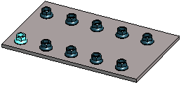
Assembly Pattern Data
Define the pattern data in the dialog box. The content of the dialog box and the features used vary depending on the pattern types.
Dialog Box Options
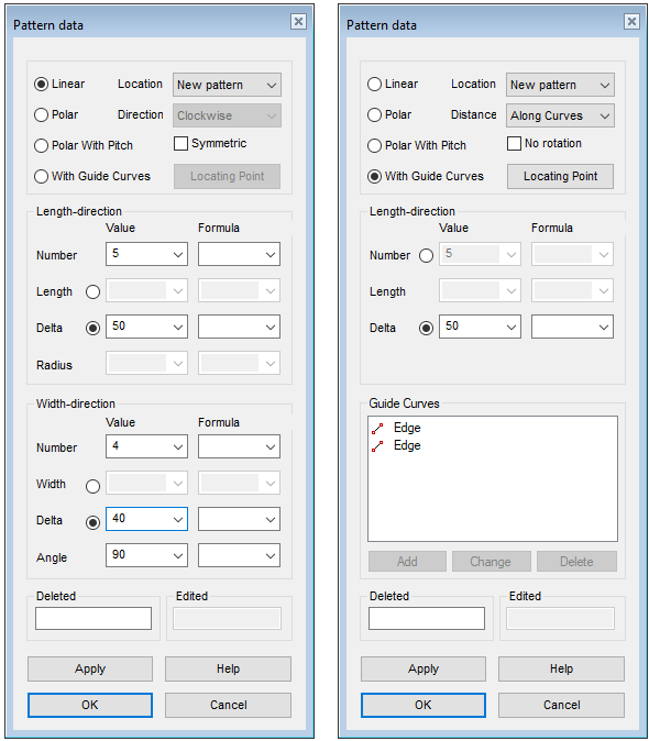
- Linear
- Defines the pattern as linear. You can define a linear pattern in an assembly in one direction or in the length and width directions.
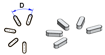
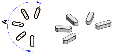
- Polar
- Defines the pattern as polar. For a polar pattern, the number of components, angle or angle spacing is specified.
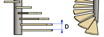
- Polar with pitch
- Defines polar pattern with pitch.

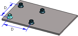
- With guide curves
- Create a part pattern along a line or tangential line chain. Select the desired lines to the Guide curves list.

- Number
- Enter the number of parts to be added in the pattern.
- For a linear pattern, separately to length and width directions.
- For a polar pattern, the number of parts on one circle.
- The total number of parts to be set on the guide curve and the polar pattern with pitch.
- Number: In the length direction of a polar pattern
- Enter the number of overlapping polar patterns.

- Formula
- Enter a variable for the pattern property (for example Number, Length, Width), which can be used when the assembly is varied using the dimension table. variable.
- Length: For a linear pattern
- Enter a value for the total length of the pattern, on which the components are placed at equal intervals. The direction of the positive X axis determines the longitudinal direction in the assembly (default). To check the directions of the axes, press the K button to change the cursor into a coordinate axis cursor. If necessary, rotate the pattern using auxiliary functions.

- You can enter either Length or Delta, one excludes the other.
- If you enter the length, the delta is calculated.
- Length: For a polar pattern
- Enter the total height of the overlapping patterns.
- You can enter the Length (L) in Length-direction or the Delta. One excludes the other.

- Delta: For a linear pattern
- Enter the distance between the parts in the the length or width direction.
- Delta: On the circle of a polar pattern
- Enter the angle between two pattern members.
- You can enter either the angle or the delta (D). One excludes the other.
- Delta: In the length direction of a polar pattern
- Enter the spacing between two overlapping polar patterns.
- You can enter the Delta (D) in Length-direction or the Length. One excludes the other.

- Delta: For the polar pattern with pitch
- Enter the "vertical" spacing between two parts.
- You can enter the Delta (D) in pitch direction or the total pitch. One excludes the other.
- Width
- Enter a value for the total width of the pattern, on which the components are placed at equal intervals. The direction of the positive Y axis determines the latitudinal direction in the assembly (default).

- Radius
- The radius defines the value of the radius in the geometry, type of guide curve, PATTERNPOLAR.
- Note that the radius value will not affect the radius of a polar pattern.
- Angle: For a linear pattern
- Defines the angle of a linear pattern.
- The angle of a symmetrical pattern is 90 degrees

- Angle: For a polar part pattern
- Defines the angle at which the components will be set at equal distances.
- You can enter either the angle (A) or the delta. One excludes the other.
- Pitch
- Defines the value of the total pitch
- Only available for types: Polar With Pitch.
- You can enter the total pitch (H) or the delta in the pitch direction. One excludes the other.

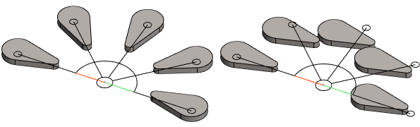
- No rotation
- An asymmetric component rotates in a pattern by default. You can prevent rotation of the component by selecting the No rotation check box.
- Only available for types: Polar and Polar With Pitch.
- The feature is rarely used.
- Locating point
- Define a point from the part or assembly that is projected to the line. The default point is the part's or assembly’s origin or handle.
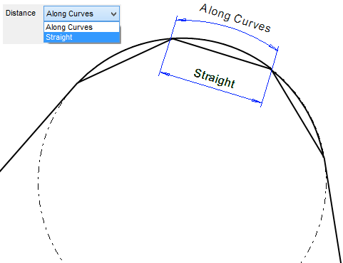
- Distance: With guide curves
- If you entered a Delta value, you can choose whether the distance is calculated Along Curves or Straight.
- Deleted
- Defines which components are deleted from the pattern. The position of the component is given as XY coordinates inside parentheses. A period (.) is used to separate the X and Y coordinates. In the Deleted field, you can enter several components to be deleted one after another, for example (1.1)(1.3). The parent component is (1.1). You can define components to be deleted when creating or editing the pattern.

 Delete a Component from a Pattern
- Edited
- When a feature pattern has been created of a local part, and a part other than the first one in the pattern has been edited, its coordinates are displayed in the Edited field just like the coordinates of a deleted component.
- Pattern Location
- Defines how the pattern is positioned in the assembly. Select one of the following options: