
Control Part
If you position the pattern using the New Pattern selection, the software will add a control part to the pattern.
- The control part for a linear pattern is
 PATTERNXY.
 - The control part for a polar pattern is PATTERNXY.
What is a control part and how do I select its location?
- The control part is the guide curve (3D sketch) of the pattern, which define the directions and relative locations of components in the pattern.
- When adding a pattern, select a point or a line in the assembly as the location of the control part.
- The control part's location will not change the location of the part from which the pattern is created.
- Based on the pattern's data and selected location, geometric constraints are automatically added to the 3D sketch of the guide curve.
- You can set visible the control part of a polar pattern in the model drawing. Select as a property of a control part
 Reference geometry visible.
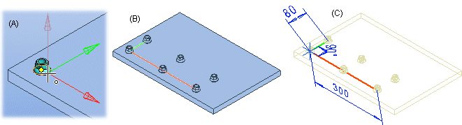
Example - Selecting the location of a control part for a linear pattern
- Select the location (A) of the control part on the component from which the pattern is created. You can also select a point that is not on the component as the location.
- The origin of the 3D sketch is placed in the selected point.
- If you select a pattern from the assembly tree, you can also see the pattern's control part (B) in the assembly.
- The colors of the guide curve's lines indicate the directions of the positive axes (C). The lengthways direction is the X axis (red) and the widthways direction is the Y axis (green).
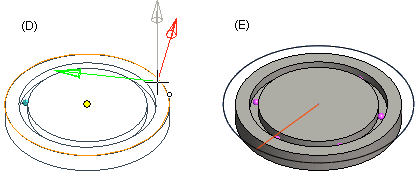
Example - Selecting the location of a control part for a polar pattern
- Select the center point of a face as the location (D) of the control part.
- The origin of the 3D sketch is placed in the selected point.
- If you select a pattern from the assembly tree, you can also see the pattern's control part (E) in the assembly.
- The circumferential guide curve is drawn as a circle if the pattern's angle is 360.
How do I edit a control part?
- After you have positioned the pattern, you can edit the directions and relative positions of the components in the pattern.
- By selecting the 3D sketch to edit, you can edit the pattern properties using dimension constraints such as length, angle or radius.
- Do not delete lines or automatically added dimension constraints from the 3D sketch.
As an example, edit the Angle constraint of the 3D sketch.
