
Model a SmartSnap Assembly Component
Library
Note the following in the modeling of an assembly component:
-
Model the SmartSnap component in an assembly
This is because the component must have geometric links to external parts when the component is saved in the component library. This requires that the component has been placed in an assembly. In this way, the external constraints connected to the component will be saved with it.
-
The first part of the component is a local Jig part
To the Jig part 3D sketch is defined the geometry which is associated to external objects (faces, points, lines).
-
Geometry logic
The external geometry of the assembly (i.e. other parts) control Start componen Jig 3D part. The Jig controls the component's other geometry. The Jig can include other features besides the first 3D sketch. The danger is creating a situation in which the other components control the Jig (loop).
-
Features to be modeled in the component
A component often has properties that are not inherited from other parts of the assembly. For example, railings have a height and stairs have a width. These are the internal properties of a component. Usually, it is a good idea to model these in the Jig. In this way, the Jig will feature all the essential information about the component's dimensions.
Basically, it is enough to bind the Jig's 3D sketch. This course it that the direction of the positioned model and direction do not change, Instead, only the 3D sketch in the Jig is moved. The the other parts in the assembly must be position separately to the 3D sketch objects. If there is a lot of these parts, binding them to the sketch takes considerable effort.
The problem is alleviated by the fact that you can position the assembly itself to objects in the surrounding geometry. The base plane of the SmartSnap component can be bound to match the geometry to be positioned. Then the Start component turn by the specified constraints after then the software resolve the the position of the 3D jig.
This is a benefit in profile structures, since the profile cross section does not need to be separately positioned to the component's Jig lines.
In addition, binds can be created between faces, which better maintain the correct handedness of the solution (point-point constraints do not have a direction, only a value).
- As na example, by the Jig 3D sketch constraints located component. The coordinates do not turn.
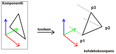
- For example, a component positioned with the constraints of the assembly. Note the turning of the SmartSnap component's (colored) coordinates.

- As na example, by the Jig 3D sketch constraints located component. The coordinates do not turn.
-
A sufficient number of assembly alternatives
The goal is that there is a sufficient number of geometry constraints in the assembly. In this event, the SmartSnap component is fully defined.
In some cases, constraints can be left undefined, which means that the component to be positioned can move according to the specified constraints and it can be finally positioned in the assembly by adding constraints.
- For example, the access bridge on the roof of a building is always parallel to the ridge of the roof. The fastening parts are aligned according to the flat face, but the position of the bridge is always situation-specific.
- For example, stairs run between two planes and the elevation is defined based on them, but the position of the stairs at the edge of the plane must be freely-definable.
- In the example cases, the assembly constraints are left incomplete. Therefore, the component can be dragged within the model, or its relation to other geometry can be determined accurately with Distance constraints.