
Add Pipe Component
Piping Design
You can select pipes, pipe parts or hoses from the component library.
 You can use straight and elbow components as as an assembly component, which first part is corresponding part model as the first part to control the other parts. This part model cannot have item data and the assembly cannot include other pipe parts.
A piping component can also be a pipe assembly. If you select a pipe assembly from the library, for more details Adding a Pipe Assembly Component.
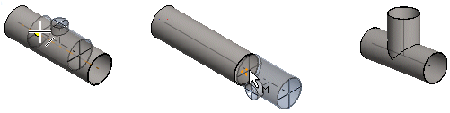
The selected pipe component is displayed in the working window. By default, a component will be positioned in the direction of the pipe's centerline when you move the component over the pipe.
- Add a component to a centerline in the pipeline.
- Add a component to a handle of the pipe.
- You can also position a component freely.
- If you have defined Connection with Flange for the component, the pipe connection will be created so that the program will prompt you to select a flange before you can continue routing the pipeline. For more information, see Pipe Connection Data.
You can also model a pipeline by selecting pipes and pipe parts from the component library. Add a pipe component to a pipeline. Select either of the following:
- Select either of the following:
- On the
 tab, in the Add group, click
  Add Component (G4).
 - On the
 tab, in the Pipes group, click Add pipe component.
- On the
- Select the component in the
 Browser.
You can only select components that are suited to the active pipe's material and size from the component library.
For example, if you select a new value in the Diameter filed and Lenght field, and select OK. The component selection is changed.
- After selecting the component, select the component properties. Select pipe component properties. If the editing of the component in a dimension table is allowed, select the Dimension table, and edit properties, and select OK.
- You can position the component on a center line or a handle. For example, a Snap function is selected.

If you wish to place the component onto a face, select the Snap function.

- Before clicking a position for the component, you can change the location of the handle, for example.
- If necessary, change the location of the handle in the component.

- Rotate the component, for example around the Z axis in 90/15° steps with the button, or the Up and Down arrow keys.

- If necessary, change the location of the handle in the component.
- As the location, click either of the following:
- Click the handle.
- If you click the center line, you can move the component along the pipe.
- You can also edit the rotation of the component, for example.
- If necessary, rotate the pipe component 90/15 degrees on the pipe.

- If necessary, rotate the pipe component 90/15 degrees on the pipe.
- Select a location for the component.
- Select Confirm.
- You can also copy one or more components and paste to a pipe assembly.
- If necessary, you can zoom the model in or out with the mouse wheel or the F6 key in order to see the end point (grip point) of the center line.
- If you are adding the component to a bent pipe between its end points, the pipe will be broken into two bent pipes.
- You can also set the component on the side of the pipe by pressing the Alt key and clicking the certerline of the pipe.