
Position Pipe Components Using Constraints
Piping Design
You can position a pipeline approximately by dragging the pipeline components. This requires that pipeline components have been fixed in position and that component directions have been fixed.
The relative locations of pipes and pipe sections, and their length in the pipeline, are defined using geometric constraints.
The following functions help in positioning components.
 Fix a Part
- Release a Part
- Release a Direction
- Fix a Direction
- Release a Rotation
- Fix a Rotation
- Define Rotation as an Angle Value
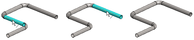
Editing a pipeline by dragging
You can edit a pipeline by dragging pipeline components one by one. If none of the components are fixed in place or component directions have not been fixed, the pipeline cannot be edited in a controlled manner.
Before editing a pipeline by dragging, fix components and their directions using geometric constraints. The direction of a pipe line added in the vertical direction (Z axis) is the only one that will be automatically fixed.
Adding constraints to a pipeline
- Begin adding constraints by first fixing the position of those pipeline components which must not move. For example, fix the positions of the pipes beginning and ending the pipeline. You can then edit the shape of the pipeline by, for example, dragging a horizontal pipe.
- Fix the direction of a component if you wish it to retain its original direction.
- Add geometric constraints between components. For example, add a Distance constraint between the centerlines of pipes.
Solving the constraints
Solving the constraints affects assemblies whose parts have features with external references.
- Move the cursor over the label of the main-level assembly in the assembly tree.
- Select the context-sensitive function
 Solve.
- You can edit the size of a pipe component with the Dimension Table function. You can also select
 Dimensions Fixed in the dimension table. This will have an effect when you are editing a pipeline by dragging one of its components. Fixed dimensions will not change. Fixing dimensions affects straight pipes and pipe elbows.