
Wall Layer Parameters
Layer parameters are available in the Wall dialog box, when you have selected a layer in the Layers list or in the preview image. If you have selected a particular wall volume in a model and opened its properties for editing, you can only edit the properties and parameters of the volume in question. You cannot select other layers.

By default, only some parameters are displayed in the dialog box. You can display more parameters as follows:
- Open the context-sensitive menu in the parameter list.
- Select Show All Parameters.
Basic Parameters
You can select the following general parameters for a layer:
-
Display in 2D - When this checkbox is ticked, the layer will be displayed in the floor plan.
-
Insulation - Defines whether the layer is insulated or uninsulated. This information can be used in material collection.
-
Can Be Stretched to Roof - When this checkbox is ticked, the layer can be stretched to a roof above it.
Frame Parameters
You can define frame parameters for a layer to be used in the wall panelizing. The parameters pass the layer properties to the frame details defined in the framing library. These parameters override the system parameters.
- Stud Spacing - You can define a parameter for the framing layer. You can use it when collecting materials to separate walls that are identical in every other way but have different stud spacing. The stud spacing is read into the material database parameter 9. The parameter value is also used in wall panel design. It overrides the default stud spacing defined in the project parameters.
- Thickness Parameter - Defines the thickness of the layer. Enter the parameter's name in the text field.
- Offset Parameter - Defines the offset of the layer. The offset is calculated to the center of the layer. Enter the parameter's name in the text field.
- Extra Parameters - Defines the possible extra parameters. Enter the parameters in the format:
PARAM1=VALUE1|PARAM2=VALUE2 ...
The parameter names and their values are optional.
Other Parameters
You can select the following parameters for each layer:
-
Surface Properties - Select a category for the layer. The category determines the surface material to be used for the layer in the model. The default category for each layer is defined in the wall layer library. The surface material of the category is defined in the rendering material library.
You can select different categories for both coarse and accurate models. The model displayed in the preview image is either coarse or accurate, depending on which presentation method you last used when adding a wall.
-
Surface (coarse) - The material will be displayed in the building model, if the wall's presentation method is coarse.
-
Surface (accurate) - The material will be displayed in the building model, if the wall's presentation method is accurate.
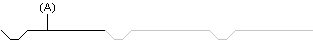
You can texture the surface of a layer with a 2D hatch in an accurate model. Draw the basic hatch shape and save it as a drawing file (*.vxp). Enter the name of the file in the Texture File field. The program will generate a machining polyline by copying the basic shape (A) repeatedly. The texture files included in the basic software delivery are in the ../system/macros/walls folder. You can design texture files of your own and save them to the ../custom/macros/walls folder.
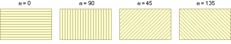
Texture Angle determines the direction of the texture hatch. Enter the desired value in the text field.
Usable Width is the rise of a single board in a cladding. The usable width is intended to be used together with the texture angle when the texture file is parametric, in other words when the width of the board is controlled with a dimension constraint. The value of the usable width is loaded as the value of the dimension constraint. This enables claddings of varying widths by using just one texture file. Solving the constraints requires that 2D Constraint Manager is enabled. The UTV/UYV cladding materials have been implemented as an example in the basic software delivery. The default value of the effective width is set in the wall layer library.
-
-
Hatch - You can add, for example, a brick hatch to a layer by enabling the Hatch property. Select a pre-made property set for the hatch from the list, or define the Type, Layer, Pen, Scale, and Color properties individually.
- Extra hatch - You can define one or several extra hatches for a layer. Extra hatch is not available for selection in the list as a default, but you can add one for a layer as follows:
- Open the context-sensitive menu in the list.
- Select Add hatch.
Enable extra hatch by ticking the checkbox next to it. Select a pre-made property set for the hatch from the list, or define the Type, Layer, Pen, Scale, and Color properties individually.
You can delete an extra hatch as follows:
- Select the extra hatch from the list.
- Open the context-sensitive menu.
- Select Delete hatch.
-
Color Fill - Color fill is enabled when this checkbox is ticked, but it will only be displayed in the floor plan when the wall parameter Color Fill for Whole Wall is not selected.

Select the color from the list or palette.
-
Select one of the pre-defined color options.

-
 Palette - Select a color from the palette. The colors of the palette are defined in the program's setup file, user/pmap.
Select the order of the colors:
- Hue Order
- Numeric order
Select a new color by clicking from the palette. The old color and the new color selected are displayed in the dialog box. The RGB value of the color is displayed on the right side of the image and its number below the image.
Preview displays the color over which the cursor is on the palette.
Click the Use Default Color button to use the default color of the element, defined in the settings.
- ACI Palette - Select a color from the AutoCAD Color Index palette.
 RGB-palette - Select a color from the palette.
Define a new color by clicking Define Custom Colors. Fill in the color properties, and select Add to Custom Colors.
The color fills will be displayed in the plan when the Show Color Fills setting is enabled.
- Select
 >
>  Preferences >
  Drawings, Models.
 - Select the View tab.
- Select Drawing:
 Show Color Fills.
-
-
Line Fill - You can add, for example, an insulation line to a layer by enabling the Line Fill property. Select a pre-made property set for the line fill from the list, or define the Line type, Layer, Pen, Scale, and Color properties individually.
-
3D Line Properties - Select a pre-made property set for the line from the list, or define the Line type, Layer, Pen, Scale, and Color properties individually.
-
2D Line Properties - Defines the properties of a layer's interior surface line. The interior surface line is always drawn for all layers. Select a pre-made property set for the line from the list, or define the Line type, Layer, Pen, Scale, and Color properties individually.
-
2D Line Properties (exterior) - Defines the properties of a layer's exterior surface line. The exterior surface line is drawn if the wall only contains a single layer, the layer is an external siding layer, or the layer is limited by an air gap. Select a pre-made property set for the line from the list, or define the Line type, Layer, Pen, Scale, and Color properties individually. If the properties of the exterior surface line are not defined, the line is drawn with the same properties as the interior surface line.
 Note
Note
- The default parameter values for a layer are defined in the wall layer library.