
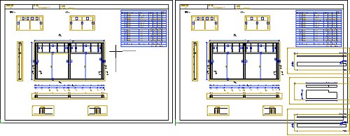
Add a View to a Panel Drawing
Framer
Add a view, cross section or schedule to a panel drawing as follows:
- Open the panel drawing.
- Right-click to open the context-sensitive menu.
- Select
 Add View to Panel Drawing.
 - Select the drawing element to be added in the dialog box.
- View
- Select one the following panel model projections as the view:
- Section
- Add a section to a panel drawing as follows:
- Listing
- Add a part schedule or a list of layers, or the part drawings of framing parts to the panel drawing.
- Select
 and the desired option from the list. The alternatives depend on the panel type (wall, floor, roof or truss panel). The available schedules are defined in the system settings. For example:
 - Select
 Layers. Click a location for the schedule in the panel drawing.
 - Select Parts. The Part Drawings dialog box is opened. Make the following selections:
Note:
- If you want to add a section with a direction other than horizontal or vertical to a panel drawing, do the following:
- Add the section as described above.
- Quit by pressing the Esc key.
- Select the section line.
- Right-click to open the context-sensitive menu.
- Select Move.
- Select a reference point.
- Rotate the line using the functions in the auxiliary menu or the cursor keys.
- Select a location for the section line.
The section drawing is automatically updated after the change.
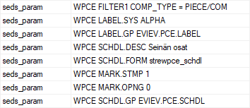
- The available schedules for each panel type are defined in the system settings with the keywords seds_set. For example, the schedules for wall panels:WPCE = Wall members
- seds_set
- WALL "WPCE|SHT|CONN"
SHT = Sheets
CONN = Connectors
The pieces to be collected to the schedule, and the format and presentation of the schedule are defined in the system settings with the keywords seds_param. For example, the wall panel part schedule WPCE:
- By default, all the sheets are collected to a single sheet schedule without separating the exterior or interior sheathing in a wall panel, for example. The pieces can also be collected by structure layers. For example, only the sheets in the sheathing layer outside the frame layer can be collected to the sheet schedule of a wall panel using the following definition:
- seds_param
- SHT1 FILTER1 COMP_TYPE = SHEET and LAYER = 1
- seds_param
- ...
- By default, the sheet code (CODE) is displayed in the sheet schedule. The material code of the sheet (MATCODE) can be used instead. Using this feature requires editing of the form file.
- It is possible to add the item codes set to the profiles to the parts schedule of the panel drawing. For example, to the wall panel part schedule as follows:
- seds_param
- WPCE SCHDL.FLD ITEM_CODE
Using this feature requires editing of the form file.
- The piece length presented in the schedules is the length of the piece's 3D geometry, if the geometry is available. If the geometry is hidden, the length is a theoretical length.