Select the settings of the horizontal structure or wall panel view in the dialog box.
You can also add a view to a truss drawing. In this case, different settings are selected for the view.
Settings of a Truss Drawing View
Tab: General
- Scale
- The size of the view area and the default scale of the view are defined in the panel drawing's template drawing. You can change the scale by selecting an option in the Scale list.
- The properties Locked, Scale Update and Align to Main View can be selected when you edit the view in the panel drawing's template drawing. In the template drawing, you can edit the size of the view area and the default scale. Editing the template drawing is the task of the system administrator.
- Edit a View Area in a Template Drawing
- Define the View Scale in a Template Sheet
- View margin
- If necessary, you can enlarge the size of the view area by setting a margin for the view. It may be necessary to enlarge the view area, if the drawn geometry exceeds the limits of the view area, and the geometry cannot be dimensioned. If you wish, you can downsize the limits as they were after dimensioning. The limits are not relevant for the appearance of the drawing as they will not be displayed in the final output.
- Select the margin from the list. When the value is 0, the view area does not have a margin. When the value is greater than 0, the margin width is the given value * the shortest dimension (width or height) of the view's geometry. The default value for panel drawing views is 0.
- Hidden Lines
- Hidden lines in a model are lines and parts of lines behind opaque surfaces in the viewing direction. Select this checkbox to display the hidden lines in the panel view.
- Restore Deleted Elements
- To restore lines deleted from the view, select the checkbox and click the OK button to close the dialog box. The lines can be restored even if you have previously closed and reopened the panel drawing.
-
Note: Deleted dimensions and section markers cannot be restored.
- Filter
- Select the geometry to be displayed in the view. Select one of the following:
- No Filters - All the components (joists and rafters, studs, sheets) of the panel, as well as the structure that determines the shape of the panel, are displayed in the view.
- Only Parts - All the components (joists and rafters, studs, sheets) of the panel are displayed in the view. The structure is not displayed.
- Layer Filter - Click the Settings button to select the geometry to be displayed for each layer of the panel separately. The button opens the Layer properties dialog box. Select the following properties:
- Layer - The field displays the sequential number of the layer. The sequential number of the basic layer of the structure is 0. Usually, this is the frame layer (FRAMING). The description of the layer is displayed in the adjacent text field.
- The layers below the basic layer in a floor or roof panel are assigned negative numbers, and the layers above the basic layer positive numbers starting from one respectively.
- The layers inside the basic layer in a wall panel are assigned negative numbers, and the layers outside the basic layer positive numbers starting from one respectively.
- The exterior trims attached to the panel are in the layer number 99, the interior trims in the layer number -99.
- The pipes connected to the panel are in the layer number 97.
- Structure - The volume that defines the shape of a panel. The default is usually OFF, meaning the structure is not displayed in the view. If you wish to display the structure, select another option from the list. The options are the same as under Parts.
- Parts - Joists and rafters, studs and sheathing. Select either regular geometry or reference geometry as the method of presentation. If you do not wish to display the parts in the view, select OFF.
- Regular Geometry - If the selected method of presentation is regular geometry, you can also choose to display the part labels and dimension the parts. To toggle the visibility of the hidden lines (lines behind the opaque surfaces in the viewing direction), select or clear the Hidden Lines Visible checkbox. Select either of the following:
- 2D - The 2D geometry of a part.
- 3D - The 3D geometry of a part.
In the example figure below, the selected method of presentation for parts (A) is 3D geometry. The default line drawing properties were used.
- Reference Geometry - If the selected method of presentation is reference geometry, parts are displayed in the view but they cannot be edited like other parts. The part labels are not displayed in the view and parts cannot be dimensioned. Reference geometry is not hidden when hidden lines are not displayed, and reference geometry does not hide other geometry. Select either of the following:
- 2DR - The 2D reference geometry of a part.
- 3DR - The 3D reference geometry of a part.
In the example figure B below, the selected method of presentation is 3D reference geometry. The line drawing properties are determined in the selected property set.
- OFF - Parts are not displayed in the view.
- Label - Part labels.
- ON - Labels are displayed in the view.
- OFF - Labels are not displayed in the view.
- Line Properties - To select line drawing properties for parts that differ from the defaults of each layer, click the Line Properties button. The button opens the Line drawing properties dialog box. When you select a property set from the list, the line properties Line Type, Layer, Pen, and Size are updated in the fields. If necessary, you can modify each property by selecting a new value from the list. The property sets are defined in the GEOMPROP keyword group in the system settings. You can edit the color of the property set in the system settings. If the field is empty, the default drawing properties are used.
-
The method of presentation of joint components in the panel drawing view depends on the method of presentation of the parts to be connected:
- If a joint component is between reference parts, it will also be displayed as reference geometry.
- If a joint component is between a reference part and a regular part, it will be displayed as regular geometry.
- If a joint component is between a visible part and an invisible part (method of presentation OFF), it will not be displayed.
- Show External Parts
- Select this checkbox to display the objects selected to be displayed in the panel drawing. The object can be a macro component, a wall, a column, or a beam, for example.
- First select Panel |
 Part Visibility to connect the object to the panel and then update the panel drawing.
- External Objects to Panel Drawing
- In the panel drawing, only the part of the object that is inside the limiting polyhedron is displayed. The edges of the limiting polyhedron extend 500 mm around the panel in every direction.
- Select one of the following as the configuration method of the parts:
- No - External parts are not shown at all.
- As separate group - The presentation method of parts in a view is displayed in the example figure.
- As a part of main group - Is suitable for using in a separate piping drawing.
- By default,
 Limits by Main View is selected. In this case, a limited configuration is used for the external parts. If you wish to display the parts in full, clear the checkbox
  .
.
- Select Grids, when you want to display a grid in the view. In a wall panel drawing view, only the grid lines perpendicular to the panel are shown. You can move the grid line label and edit the label properties in the view.
- Grids
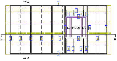
- You can select the windows, doors and opening trims to be shown as external parts in the wall panel settings before you generate the panels. On the Attach tab, select the option Visible for the desired parts.
- Generate Wall Panel Breaks
- Trusses can also be shown as external parts in the view of a wall panel drawing.
- Truss Locations in Wall Panel Drawing
Tab: Options
- Show Mounting Boxes
- Select the visibility of mounting boxes:
- No - Boxes are not shown.
- In front of view - Boxes in front in the viewing direction are shown.
- In back of view - Boxes in behind in the viewing direction are shown.
- All - All boxes are shown.
- The program will add the mounting box on its own layer. If the layer is not displayed, the symbol will not be displayed in the panel drawing. In the standard software delivery, the layer is 164 Panel Elev./Electr.
- Add an Electrical Box
- Select Layers from List
- Show Electrical Pipes
- Select this check box to display the electrical pipes in the panel view.
- Add an Electrical Pipe
- Machining Accessories
- Select this checkbox to display the details required for manufacturing the panel, such as nails, saw lines, millings, and glues in the panel view.
-
Note: Requires a customer fitting.
- Insulation
- Select this checkbox to display the insulation in the panel view.
- Insulation Labels
- Select this check box to display the insulation labels in the panel view.
- Show Openings
- Select the check box to display windows and doors attached to the panel with their labels in the wall panel view. You can select the windows and doors to be attached to the panel in the panel settings before you generate the panels. On the Attach tab, select the option Yes for the desired parts.
- Generate Wall Panel Breaks
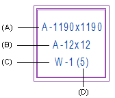
- You can add the opening sheet label of a window or a door to a wall panel drawing. The format of the opening sheet label can be defined in the system settings with the keyword op_label_format, for example:
- op_label_format= "#CODE#|#IDLABEL# (#LABEL_IND#)"
- #CODE# is the opening code in the library (A)
- #LABEL# is the opening label in the library (B)
- #IDLABEL# is the opening sheet label (C)
- #LABEL_IND# is the label that identifies the opening sheet (D)
- Adding a vertical bar will enter a line change in the panel drawing.
- Notes
- You can add note text macros to the panel. Select the check box to display the note text in the view.
- Show Gravity Point
- You can mark the gravity point of a panel in the view of a panel drawing.
- Gravity Point of a Panel in a Panel Drawing
- Edge Angles
- Select this check box to display the angle of the oblique edge of a floor or roof panel in the view. The angle value will be displayed in the main view.
- Pipes
- Select this check box to display different kinds of connection macros in the panel view.
- Above Interior Walls
- Select this check box to display the interior walls above the floor or roof panel in the panel view.
- Below Structures
- Select this check box to display the structures below the floor or roof panel, such as walls and beams, in the view.
- Above Trusses Visible
- Select this check box to display the roof trusses above the floor or roof panel in the panel view.
- Below Trusses Visible
- Select this check box to display the roof trusses below the floor or roof panel in the panel view.
Tab: Mount
- Show: Loose Part, Mount Manually, Manually Placed
- Parts with a different mounting method are shown in the panel drawing when you select the mounting method check box:
- Loose Part - A part to be mounted at the building site.
- Mount Manually - A part to be manually placed and mounted in the factory.
- Manually Placed - A part to be manually placed but automatically mounted in the factory. You can use this mounting method for parts that the production line cannot automatically position due to the size or shape of the part, but over which the nailing and glue lines must continue.
- You can select line drawing properties for parts that differ from the defaults by clicking the Line Properties button. The button opens the Line drawing properties dialog box. When you select a property set from the list, the line properties Line Type, Layer, Pen, and Size are updated in the fields. If necessary, you can modify each property by selecting a new value from the list. The property sets are defined in the GEOMPROP keyword group in the system settings. You can edit the color of the property set in the system settings. If the field is empty, the default drawing properties are used.
Note:
- Line font in the section view is affected by the value of the keyword use_line_sort_and_scale_for_sections in the 3d keyword group in the system settings:
| use_line_sort_and_scale_for_sections = 0 |
The line font is a continuous line. |
| use_line_sort_and_scale_for_sections = 1 |
The line font and scale selected in the view properties are used. |
- When you select dashed as the line type, the drawing of the line is affected by the setting Fast drawing of dashed lines. When the fast drawing of dashed lines is enabled, the line will be drawn on the screen and printouts in the same way, regardless of the line's Scale value or the drawing's scale.
- Define an Exceptional Mounting Method for a Part
- Mark Exceptional Parts
- Fast Drawing of Dashed Lines
- Draw as a separate group
- With the feature, you can force visible parts that would otherwise not be shown in the view. For example, in a sheathing view, you can display the loose parts behind the sheathing by selecting the 3D method of presentation for the parts of the layer in question, loose parts visible and this feature in the view properties.
Tab: Draft
On the Draft tab, you can define drawing properties for the lines in the view and the presentation of the part lables according to certain rules.
- Selection
- The rules that define the drawing properties of the lines or the presentation of the part labels in the view are stored in a component library. Select the library and rule in the browser by clicking Select.
- The basic software delivery includes the rule libraries:
- View line property rules, i.e. drawing properties of lines (VIEW_LPROP_RULE).
- Panel view modification rules, for example presentation of labels (VIEW_LABELS).
- Select a rule saved in the library. When a condition defined in the rule is true, specified drawing properties are applied for parts or labels. One file can contain several conditions. A condition may be, for example:
- If the material thickness of a part is 0.95, it will be drawn with a line named PIECE.DDD in the line settings of the system, but with a line thickness of 0.5 and a color of 134.
- Rules can be drawn up as a customer fitting. The rules are saved in an XML file in the rule library.
- For example, following rules are included in the basic software delivery:
- View line property rules
- ASSEMBLY - Hide parts without an assembly part definition. Only parts that belong to a sub assembly, such as parts that belong to an opening assembly, are drawn in the view of a wall panel drawing.
- BEAM_COLUMN_ONLY - Hide parts that are not beams or columns.
- BUILDING_COMPONENT - Hide components of type COMP_MACRO.
- ELEC_PIPE_LINE - Draw the line of an electrical pipe as follows:
- With a continuous line, when the electrical pipe is on the nearest surface in the viewing direction of the panel.
- With a dashed line, when the electrical pipe is on the opposite side of the viewing direction.
- GAUGE - The drawing properties for the parts are defined according to material thickness.
- Panel view modification rules
- BEAM_PNL_LBL_LEADER_LINES - Change the labels of beam panels to reference line labels.
- OPENING_LBLS - Use the library and drawing file defined in the rule for the opening labels. The view property Show Openings must be selected.
- Clear
- Click Clear to remove the selected rule for the view.
