
Add an Electrical Pipe
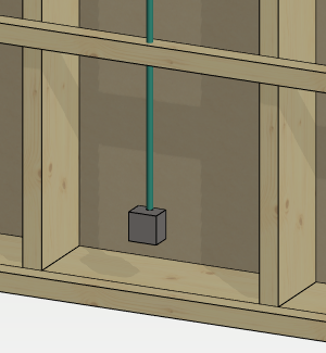
You can add an electrical pipe to a wall panel in the framing model after you have first added an electrical box to the wall in the architectural model, see Add an Electrical Box. A mounting box is added to the framing model for the electrical box, which you can select to add an electrical pipe.
An electrical pipe is a profile that is added from the profile library pipe_electrical.
Add an electrical pipe as follows:
- Select the mounting box in the framing model.
- Right-click to open the context-sensitive menu.
- Select
 Add Electrical Pipe .
 - Select the profile cross section from the Code list.
- Click the points of the pipe's centerline.
- Select Confirm.
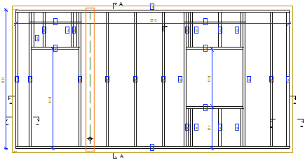
Electric pipes appear in the panel drawing view when you select Show Electrical Pipes in the view properties. In the view properties, you can also define the drawing properties of the electrical pipe lines by selecting a rule library and a rule. The standard software delivery includes the rule library VIEW_LPROP_RULE, which contains the rule ELEC_PIPE_LINE for electrical pipes. With this rule, the line of the electric pipe is drawn as follows:
- With a continuous line, when the electrical pipe is on the nearest surface in the viewing direction of the panel.
- With a dashed line, when the electrical pipe is on the opposite side of the viewing direction.
Note:
- You can generate holes in the frame and sheathing parts of the building according to the pipeline you have added, see Generate Utility Holes.
- You can create a selection group of the mounting box and electrical pipe that you can mirror, copy, and move in the framing model. You can save a selection group to the component library by creating a building group from it. Select Electrical component as the input style of the group.
- You can select the object group Mounting boxes and electrical pipes to be included in the drawing generation model, so that the mounting box and electrical pipe appear in the views generated from the model.