
Add an Electrical Box
Framer
Add an electrical box to a wall as follows:
- Select Modeling | Accessory Component | Component gallery

 Component.
 - Select the folder Electrical in the browser.
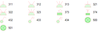
- Select a component by double-clicking its thumbnail. Select a component of type "506 Electrical box". In the standard software delivery, these include:
- Select the electrical box properties in the dialog box.
General
Select the general properties.
- Floor plan symbol - Select the symbol to be added to the floor plan drawing of the building from the list.
- Distance from wall - Type the distance of the floor plan symbol from the inner surface of the wall in the field.
- Elevation drawing symbol - Select the symbol to be added to the panel drawing of the wall panel from the list. The symbols added at the back of the panel in the viewing direction are marked with a dashed line in the panel drawing.
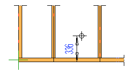
- Height from bottom - Select the height of the elevation drawing symbol from the
floor level from the list, or type the desired value in the field. Later, when you create a panel drawing
and add a dimension line for an electrical symbol, the dimension will display the distance of the symbol
from the bottom of the wall panel.
- Material code - Select from the list.
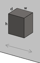
- Box height (h), Box width (w), Box
depth (d) - A mounting box is added for the electrical box in the framing model. Type the
dimensions of the mounting box in the fields.
 Note: The component has a different presentation in the architectural and framing model.
Hole
If the NC Link add-on option is available to you, you can transfer the installation hole to the production control system. Select the installation hole properties:
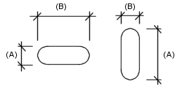
- Shape - Select one of the following shapes of the installation hole:
- Circle - Type the radius of the circle in the Circle field.
- Rectangle - Type the dimensions in the Height and Width fields.
- Obround - Type the dimensions in the Height (A) and
Width (B) fields.
- Depth - Select either of the following depths of the hole:
- Through - The installation hole goes through the wall panel.
- Enter the depth of the hole in the text field.
Note: The installation hole is displayed as line geometry in the framing model after you have created the wall panel and added the NC accessories to the wall panel. If you move the electrical symbol, update the installation hole geometry by re-adding the NC accessories to the wall panel. - Confirm by clicking OK.
- Select a wall.
Note:
- You can relocate the component by dragging the grip point before generating the panel breaks.
- If you move the electrical box from one wall panel to another, connect the it to the new wall panel by using the function Update Connected Parts.
- The program will add the mounting box on its own layer. If the layer is not displayed, the symbol will not be displayed in the panel drawing. You can display the symbol by making all layers visible using the
 All Layers function on the tool strip.
 - You can add a dimension line in the panel drawing to dimension the electrical box vertically or horizontally. Select Electrical symbols (ELBOX) as the dimension line to be added. Select the position and the direction of the dimension.