
Move a Log End
Log House Design
You can stretch or shorten a log by moving the log end from the grip point in the model window.
You can move the ends of several logs as follows:
- Do either of the following:
- Select a wall in the model. Select Log Wall | Wall End |
 Move Log
End.
Move Log
End. - Open the elevation of the log wall. Right-click to open the context-sensitive menu,
and select Move Log
End.
- Select a wall in the model. Select Log Wall | Wall End |
- Select the end of a log. Select several logs with the Ctrl key down.
 In the example A below, the log
ends are clicked in the model. The log ends on the left side of the cutting point in the
wall are selected for moving. In the example B, the log ends are selected in the wall
elevation by selecting an area. Select the area so that the cutting point in the wall is
inside the area. All log ends at the cutting point will then be selected.
In the example A below, the log
ends are clicked in the model. The log ends on the left side of the cutting point in the
wall are selected for moving. In the example B, the log ends are selected in the wall
elevation by selecting an area. Select the area so that the cutting point in the wall is
inside the area. All log ends at the cutting point will then be selected.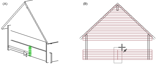
- Select Confirm. The log you selected first is attached to the cursor, and the cursor is constrained in the direction of the wall. You can move the log end by moving the cursor. In this guide, the log is called a reference log.
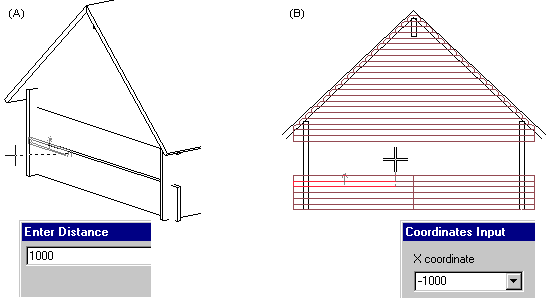
- Click the new location. Select a location for the end of the reference log by using the
cursor. You can also type an offset or the coordinates of the new location on the keyboard.:
- First, move the cursor in the offset direction in the model and type the offset in the text window (A).
- In the elevation, type the coordinates of the new location in the coordinate dialog box (B).
 The same offset is applied to all
selected log ends: if the reference log is shortened, all logs are shortened; if the
reference log is stretched, all logs are stretched. The offset direction is not therefore
dependent on the coordinate system.
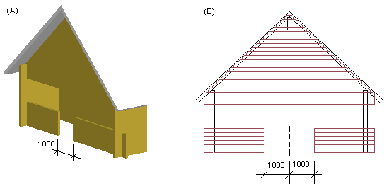
The same offset is applied to all
selected log ends: if the reference log is shortened, all logs are shortened; if the
reference log is stretched, all logs are stretched. The offset direction is not therefore
dependent on the coordinate system.In example A, the log ends on the left side of the cutting point were selected for moving. An offset was defined for the reference log, shortening it by 1000 mm. All selected logs are shortened by the same amount. In example B, log ends on both sides of the cutting point were selected for moving, and the reference log was shortened by 1000 mm. All selected logs on both sides of the cutting point are shortened by the same amount.
 Note
Note
- In the model, you can also select the function from the context-sensitive menu of the log wall.
- Open the log wall elevation with the Edit Log Wall Shape function.
- The parts of the log wall displayed in the floor plan are defined using limit heights. If you are moving the end of a log that is outside these limit heights, the change will not be displayed in the floor plan. Select Log Wall Limit Heights.
- When you are moving log ends at the end of a wall, you can restore the moved ends back to their original positions by using the Set Log Wall End Shape function. In the dialog box, select Basic end as the end shape.
Example