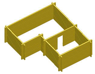
Example: Add an Opening to a Log Wall
In this example, a wall is edited in an elevation drawing. Create the opening as follows: first cut the logs at the center of the opening to be created. Then move the log ends at the edges of the opening so that the width of the opening becomes 1000 mm.
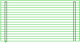
Open the Elevation of the Log Wall
- Select a log wall.
- Right-click to open the context-sensitive menu.
- Select Log Wall | Log Wall |
 Edit Shape. The elevation of the log wall is opened in a separate drawing window.
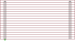
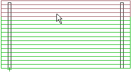
Cut the Logs
- First, select all the logs in the wall by limiting an area.
- Unselect the logs at the top of the wall. Select the logs at the top of the wall one by one while holding down the Ctrl key.
- Right-click to open the context-sensitive menu.
- Select
 Cut Log.
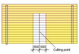
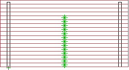
 - Select the cutting point. In the sample figure, the center point of the wall is selected by snapping to the center point of the log's edge line with the cursor. When the cursor's appearance is as depicted in the picture, click the left mouse button.

The selected logs are cut.

- Exit the function by pressing Esc.
Move a Log End
- Right-click to open the context-sensitive menu.
- Select
 Move Log End.
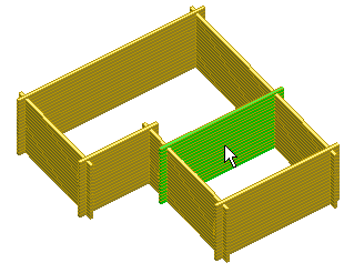
 - Select the log ends you want to move using area selection.

- The ends of all logs at the cutting line (both on the left and the right) are selected.
- Select Confirm.
- Click the new location.
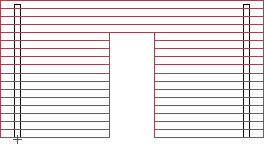
The log selected first is attached to the cursor, and the cursor is locked in the direction of the wall. Type an offset for the log end in the coordinate dialog box. The dialog box will open when you press a numeric key on the keyboard. In the picture below, the offset is selected for a log on the left side of the cutting line. The log is shortened, i.e., the log end is moved 500 mm in the direction of the negative X axis. That is, -500 is typed as the X coordinate.
 Note: If you are editing the wall in the model, first move the cursor in the positive direction of the offset and then type the offset in the text window.
All log ends at the cutting line were selected, which means that the same offset will be applied to all of them, i.e., all logs are shortened by the value of the offset. The log ends on the left side of the cutting line are moved 500 mm to the left and those on the right side 500 mm to the right. The width of the opening will therefore be 1000 mm.
- Exit the function by pressing Esc.
Return to Floor Plan and Model
- Close the elevation of the log wall.
- Save the changes by selecting Yes in the message box.
The wall geometry is updated in both the floor plan drawing and the model.