Bend
Advanced Face Modeling Package
You can bend the model according to the specified radius or angle around a particular bending axis in proportion to the reference level.
- To a part model, which could be a sheet-metal part, but this is not necessary. Stretching related to sheet-metal design is not taken into account, for example.
- To a face model
- On the
 tab, in the Deformation group, select
  Bend.
Bend. - Define the Bend Data in the dialog box.
- Click OK.
In Context-sensitive Menu
- Select the part.
- Select a planar face, which has diverging end points projected to the plane.
- Select the context-sensitive function
 Bend.
Bend. - Define the bend data in the dialog box.
- Bend angle
- Bend Radius
- Select the side of the bend. By clicking the Side button you can change the side of the bend. The arrows in the model indicate the side: right, left, both.

For example, if both sides are selected, the model bends symmetrically on both sides of the axis.
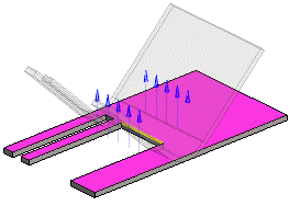
- Select the direction of the bend. You can reverse the direction. Arrows are displayed on the model to facilitate the selection.
- Limit the effective area, if necessary.
- Select the faces/lines (bending area) of the object that you wish the bending function to move.
 Select the lines from the side of the bend.
 - If you have set the bend to occur on both sides, limiting the area has no effect.
- Select the faces/lines (bending area) of the object that you wish the bending function to move.
- Click OK.
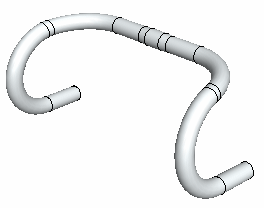
Example: Handlebar
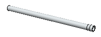
You can create a handlebar by bending a pipe part two times and then mirroring it.
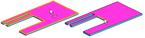
- First bend: Reference face, Rotation Axis, Direction.
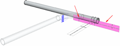
After bending.
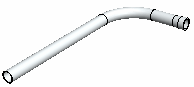
- Second bend: Reference face, Rotation Axis, Direction.

After bending.
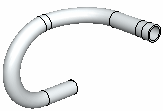
- Mirroring.