
Part Properties Dialog Box
General
- You can define the properties of a part, profile part, sheet metal part, composite sheet, pipe component.
- You can also change some of the properties during modeling.
- You can only edit the part properties in the model window, not in the drawing.
Open the dialog box
Select the context-sensitive function  Properties or
Select the part symbol in the feature tree and select the context-sensitive function Properties.

Dialog Box Options
- Name (Label)
- The part name displayed is the archive name of the model.
- Archives Data
- Click the button and the model archive data of the part is displayed for viewing and editing.
- If necessary, edit and supplement the archives data and confirm the data.
- Item Data
- Defines the part's item data that is collected in the parts list of the drawing of the part and the assembly
- Part Data
-
- This button is displayed, if the keyword set.partprop.partdata= 1 is defined in the file user/Setup.
- To Assembly Parts List
- Sets the compilation of part data into parts lists.
- Default
 the part data is collected into the parts list.
 - Clear the option
 if you do not want the part to appear in the assembly parts list.
- Default
- To Assembly Drawing
- Sets the part to be displayed in the assembly drawing.
- Default the part is visible in the assembly drawing
- Clear the option if you do not want the part to be visible in the assembly drawing.
- Default
- Reference geometry visible in the drawings of the assembly
- The reference geometry are 3D sketch, guide curves, and cross-sections, and pipe part center line.
-
- The auxiliary geometry is visible in the drawing.
- The auxiliary geometry is not visible in the drawing.
- Selection affects all drawings and drawing projections created from the part.
- However, in a drawing, you can define the visibility of the auxiliary geometry per projection.
- To Collision Detection
- Specifies whether or not to consider the part in collision detection. Such colliding parts are the collision of screws and nut threads, which should not be taken into account in collision detection.
- The geometry of the part is considered in the collision detection.
- The geometry of the part is not considered in the collision detection.
- Perform a Dynamic Collision Detection
- Detect Static Collisions
- Table Model (multiple items)
- If you create two items for a part (requires that the part has at least two configurations), then the part model becomes a table model.
- This is just an informative option
 . You cannot select or clear it.
 - If it is a table model, you cannot define part data with the button Part Data.
- Parts Lists for Product Variants (G4)
- This is just an informative option
- Machining with feature in assembly
- Defines a part property that allows or prevents the machining of a local part in an assembly.
-
- Allowed allows a local part to be machined with tool geometry.
- Allowed does not allow a local part to be machined.
- Allowed also as a link allows a link part to be machined.
- Allowed also as a link does not allow a link part to be machined.
- Makes machinings only to parts in the same subassembly
-
- You can select this property, if you select Tool as the part type.
- You can select this property, if you select
- The tool geometry of a part only machines parts in the assembly that are in the same subassembly or subassemblies under it.
- The machining also targets other parts of the assembly.
- Type
- Select the type of the part. The type brings some functionality to the part
 Normal Regular part.
- Composite Sheet The sheet-like part is a composite sheet, which can be one-, two- or three-layer.
- We recommend modeling the part using the Extrude as Composite Sheet function, which at the same time sets the part type to composite sheet.
- By clicking the Properties button, you will get the properties of the composite sheet for editing.
- Sheet Metal
- Selecting this type enables the sheet metal functions.
- You can change sheet-metal part as the part type for a sheet-like part (Normal part).
- This change is possible for sheet-metal parts that have been modeled using the Extrude function.
- You can extrude a sketch line or a continuous chain of lines into a sheet metal part by selecting the Thin Feature operation for the sketch.
- By clicking the Properties button, you will get the properties of the sheet-metal part for editing.
- Concept PartThe concept part is a technique designed to lighten heavy assemblies. An entire subassembly can be replaced by a single part, which can have sufficient detail for, for example, a layout drawing. This technique enables quick generation of sufficiently accurate drawings for tender purposes with the design automation system.
- Profile part.
- When you add a profile, the part automatically gets the definition Profile part.
- When you add a profile, the part automatically gets the definition
- Tool. The function defines the entire geometry of the part as a tool.
- If the part already contains a machining feature, you can define the entire geometry of a part as a tool only when you have first deactivated the tool property of the machining feature. You can do this in the properties of the feature in question.
- You can also define a part imported to this program as a tool, if you first save it as a Vertex model.
- Flow part. The part is a part saved in the document archives of the Flow system.
- The checkbox of the Flow part is selected when you view the properties of a part selected for editing from the Vertex Flow system.
- If the checkbox is cleared, the part's saving location is the Vertex G4 archive.
- The contents of the checkbox are changed by the program.
- Lamp. The function defines as a lamp a part to which point and spot lights have been added with rendering functions.
- The feature requires the Rendering add-on option to work.
- As a library component, the light intensity of a lamp can be adjusted in an assembly.
- Pipe component. This function can be used to define a part as a pipe component.
- This property is selected, if the pipe component is added from the library.
- Open the pipe component properties for viewing by clicking Pipe comp. info.
- Profile part.
- Properties
- After you have selected part's type, click the Properties button.
- Section is not made in assembly drawing
- The part is not cut if it is on the cutting line in the assembly drawing.
- The part is cut if it is on the cutting line in the assembly drawing.
- Transparent in assembly drawing
- The part is drawn transparent in the assembly drawing
- The part is drawn in the assembly drawing as a normal part.
- Section - hatch
- Sets the type of the section hatch in the section projection.
- Use the preset button
 to open a list of section hatches.
 - Click a row to select a section hatch.
- Use the preset button
-
Note:
If you have changed the section hatch in the model drawing with the function Hatches >
 Hatch and want to restore the hatch defined in the part properties
- First, remove the section hatch from the drawing projection.
- Select the context-sensitive function Update.
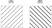
- Section - scale
- Sets the scaling of the section hatch. The factor will affect the line gap of the hatch.
- Select or enter the factor value.
- The default scale factor value is 1.
- A factor greater than 1 increases the line gap of the hatch.
- A factor less than 1 but greater than 0 decreases the line gap of the hatch from the default value.

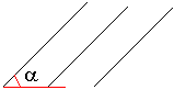
- Section - rotation
- Sets the angle of the section hatch.
- Select or enter the angle value.
- The default value is 0.
- A positive angle value will rotate the hatch counterclockwise.
- Rendering Material
- The rendering material added with the Rendering add-on option is shown in the Name field.
- Use the Change button to change the rendering material.
- Rendering Material Dialog Box
- Symmetric
- Symmetry affects the assembly function Mirror.
 Maybe symmetrical. The part behaves like a non-symmetrical part.
- Not a symmetrical part.
- Symmetrical part.
- See: Mirror a Part or an Assembly
- See the example: Example of Mirroring in an Assembly
- Named elements
- You can view named elements of the part by clicking the View button.
- Named elements include a grip point that controls the positioning of library features and components. Part Handle.
- The other named elements are related to the functionality of product automation systems.