
New Projection Dialog Box
General
- The dialog box is opened when you add a new projection model in the drawing.
- See also Dialog Box: Projection Settings.
Dialog box options
The projection is named automatically. The name is formed from the name of the model and projection, for example.
- Projection name
- The program will automatically assign the name. VIEW1, VIEW2 …, SECT1, SECT2 …. DET1, DET2 ...
- You can also enter the name yourself.
- You can also change the projection name later.
- The name appears in the drawing’s feature tree under
 Projections.
- Header
- The header text will be set as the header of the projection. The header text is automatically added to a section projection (for example A-A). For other projections, the header is blank by default.
- You can enter the projection header text and edit it later.
- The program positions the header text of the projection automatically, but you can drag the text to a new location if necessary. You can also use grip points to move the header text, see Move Text from a Grip Point.
- When you drag a projection, the header text slides along.
- Scale
- The projections default scale is the scale selected for the drawing.
- Select a suitable scale. You can also enter a different scale if necessary.
- The projection scale is shown under the projection header if a header has been assigned to the projection.
- Scale: autofree or autofix – Dynamic projection.
- Configuration
- Select the configuration of the part to be shown in the projection, if there are several configurations in the model. By default, the program offers the configuration that was active when the drawing was created.
- If you select
 Perspective, automatic dimensioning cannot be selected.
About projection:
- Direction
- Select the viewing direction from the list: Front, top, left, right, etc.
- Select the
 preset button under a: Front, which opens the list of directions to choose from.
 - Select direction
- Select the
- Viewing direction
- You can define another viewing direction by selecting the Viewing direction function. You can determine the viewing direction using the Alpha, Beta and Gamma angles, or by clicking it from the model.
- Click Select at Model to point the direction from the model.
- The program opens the dialog box Viewing Direction.
- You can select a surface from the model, so that the selected surface appears in the projection in a perpendicular position.
- Select
 Attach to surfaces if you want the direction of the projection in the drawing to change if the direction of the surface selected in the model changes.
 - If you want an axonometric or perspective projection of the model from exactly the direction where the model is, then instead of selecting the surface, select the function Confirm (Confirm = V key or middle mouse key or context-sensitive function
 OK.)
OK.) - Click OK to accept the selected viewing direction.
- Click Select at Model to point the direction from the model.
- Perspective
- Shows the projection in perspective.
- You may have to change the scale of the projection in order to get a suitable size of the perspective projection.
- Automatic dimensioning is not available for perspective projection.
- Exploded view
- The exploded view can be selected for a projection of an assembly drawing.
- Note that the explosion must be defined in the model.
- See Explode an Assembly.
Options for presentation
- Presentation
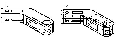
- The default drawing mode of the projection in a model drawing is Wire frame, unless another drawing mode was selected when creating a new drawing from the model. You can also select the drawing mode of a perspective projection in the drawing.
- Wireframe: A line drawing. Allows dimensioning of the drawing
- Shading: A quick way to produce a drawing, but does not allow dimensioning of the drawing. You can influence the properties of the shaded projection by selecting Advanced, which opens the Advanced dialog box.
- Precision: You can use the preset button to select the precision of the pixel image (500: fast, 2000: normal or 4096: best) or you can enter the precision yourself. The greater the number you select or enter, the more time it takes to draw the projection.
- Remove background: Removes the background that appears in the model, such as gradient.
- Anti-aliasing: Edit the drawing of edge lines.
- Use extended photorealism: Draws shading more realistically.
- Edges visible: Adds edge lines, which however do not allow dimensioning.
- Precision: You can use the
- Shading+Wireframe: When this drawing mode is selected, you can dimension any other projection except a perspective projection.
- With the Advanced settings , you can select the options shown above, except for Edges visible.
- LightWorks shading: The projection shows all the visual features enabled by the option, such as lighting, shadows, fogs, backgrounds and foregrounds.
- Requires the Rendering add-on option.
- By using the Advanced settings, you can remove the background or remove shadows.
- LightWorks Shading + Wireframe: When this drawing mode is selected, you can dimension any other projection except a perspective projection.
- Requires the Rendering add-on option.
- By using the Advanced settings, you can remove the background or remove shadows.
- Advanced
- Can be selected for all other drawing mode except Wire Frame.
- See the previous section for more details.
- In PDF and PostScript (driver code 7 5) printing, projections shaded and visualized with resolution value 0 have their original resolution in the printout regardless of the sheet size used in printing.
- Tangential lines
- Apparent shape lines will be created between tangential faces. Select drawing as a shape line or thin line, or disable the drawing of tangential lines in the projection.
- Hidden lines
- The hidden lines are drawn with dashed lines.
- Colored Hidden Lines - You can define the color of the dashed lines being hidden in the Settings.
 Define the Color of Hidden Lines
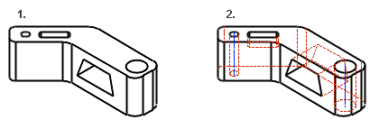
- Auxiliary geometry
- The selection shows the auxiliary geometry in the model. Auxiliary geometry is 3D sketches, guide curves, and cross-sections.
- Machining features
- A machining feature is displayed in the projection if you select Machining Features.
- The visibility of machining features in the model does not effect their appearance in the projection of the drawing.
- See Machining Feature.
- Gravity center
- Shows the center of gravity added to the model in connection with the mass calculation in the drawing projection.
- Exact silhouette lines
- The silhouette lines (edge lines) are drawn exactly.
 Coarse drawing speeds up refreshing the projections, but, for example, the dimensioning of an arc will fail.
- Especially in the projections of large assembly models, you should not include exact silhouettes, as they can slow down the drawing of the projection significantly.
- Also for spline surfaces
- Precise silhouette lines (edge lines) are drawn for the part's spline faces.
- The option is only visible if Exact silhouette lines is selected.
- Centerlines
- Center lines are automatically drawn for circles and arcs.
- Center lines of the arc will be drawn when the arc sector meets the minimum default value: 180 degrees. You can change the value of the sector projection-specifically.
- Center lines will be drawn in the projection of a part drawing, even if the
 Center Lines option is unselected when creating a new drawing.
 - You must specifically select Center Lines in the projection of an assembly drawing, if it has not been selected when creating a new drawing of a model.
- Note that it is not recommended to use centerline drawing in assembly drawings, as it can significantly slow down the drawing update.
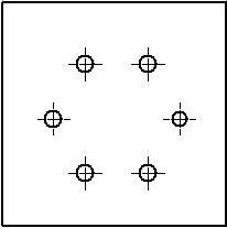
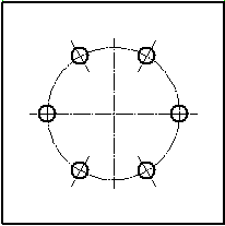
- The center lines of a polar hole pattern
- The drawing of polar hole patterns follows the mechanical engineering rules.
- In the sketching mode, define the radius of the feature pattern to the desired value, if you have used the default value (R100).
- The radius is displayed in the projection if Auxiliary geometry is selected.
- When you select Centerlines and Auxiliary geometry, the centerlines of the part are drawn in the projection through all the geometry. Can also be selected for pipe parts.
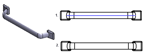
- Centerlines for pipe parts
- The centerlines of pipe parts will be visible in the projection.
- The visibility of the pipe part center lines is also affected by the projection property Auxiliary Geometry.
- When you select Centerlines and Auxiliary geometry, the centerlines of the pipe parts are drawn in the projection through all the geometry.
- Centerline offset
- You can select an offset for centerlines:
- Absolute offset, allowing you to enter the offset in millimeters.
- Relative length, where the length of the centerline is determined by the size of the circle or arc
- Automatic dimensioning
- You can add dimensions to an active projection of a drawing automatically.
- Automatic dimensioning is available when you edit the projection properties, but not when you are adding a new projection to the drawing.
- Automatic Dimensioning