
Create a Profile Structure for a Pipe Laser Machine
General
With the introduction of pipe laser machines, a new way of working has become available for the production of profile frames.
- In the older method, the profiles are first cut and then welded together in a jig.
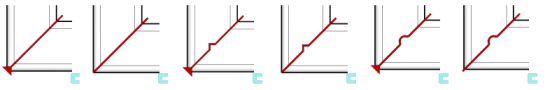
- A newer method is a method in which the desired shape is cut with a laser at the bending points of the profile. The machined profile is bent into a frame, which is then welded.
- This method reduces the need for welding jigs.

Main stages
- Start a new assembly.
- Add a new guide curve part in it. Jig (skeleton).
- Add the profiles.
- Trimming does not need to be used during the insertion phase.
- Trim the profiles to library parts.
- Use the Trim Parts > Pipelaser parts in the library.
- Select the end-type library part at the point where the ends of the pipe are together after bending.
- For more details, see: Trim Profiles to Library Parts
- Use the Trim Parts > Pipelaser parts in the library.
- Select one profile.
- Select the following contextual function: Other Exports > Profiles to stp file.
- Enter a name and select a storage folder.
- The program assigns a default name to the step file, beginning with the model name and ending with the profile index number.
- The index number describes the order in which parts are added to the assembly.
- The program assigns a default name to the step file, beginning with the model name and ending with the profile index number.
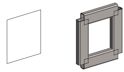
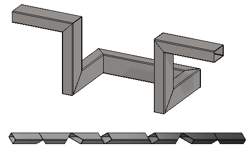
An example of a simple frame
- The image shows the guide curve part and the profiles that have not been trimmed.
- Profiles may also be trimmed.
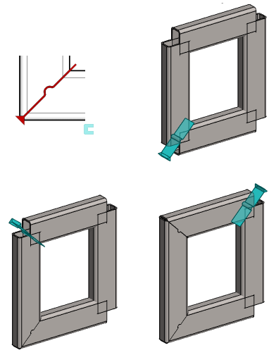
- Trimming to the library part will perform the trimming again.
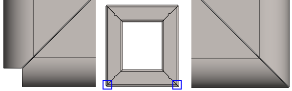
- The image shows the first three joints of the profile frame trimmed into the library part Pipelaser3.
- The angled profiles are selected in pairs.
- The library part Pipelaser3 cuts from the outer corner by the wall thickness (t) of the profile, as long as you remember to enter the correct value for the library part during the trimming phase.
- If necessary, you can restore the library part visible and edit its dimension table data if you later want to change the shape of the trim.
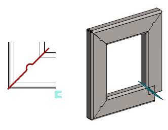
- The images shows the last corner of the profile frame trimmed into the library part Pipelaser3_End.
- The library part Pipelaser3_End does not cut off the profile wall thickness from the outside corner.
- The image shows the printed step file.
- The file has been printed with the context-sensitive function: Other Exports > Profiles to stp file.

Note: The step file is an "output" and is therefore not found in the Vertex model archive.
- If you wish, you can import and view the stp file generated above to the Vertex window.
Note: You can cancel the trimming to library parts as follows:
- Restore the library parts from the feature tree with the context-sensitive function: Restore All.
- Select the library parts and remove them with the context-sensitive function:
 Delete
 - Remove the trimming with the function: Solve.
Note: Self-study material is related to this topic. Go to the page https://kb.vertex.fi