
Example: An Assembly Machined by a Tool
As an example, a machining feature machining parts of an assembly.
- Sketch a line and define it to be a guide curve. The guide curve can also be used in positioning the machining feature in the assembly.
- Add a sketch onto the guide curve and extrude it. This extruded feature does not have a machining effect. Model a machining feature after this.
- Add a new sketch, a circle, and extrude it. Select

 Make Tool in the extrusion properties. Save the completed tool into the component library by selecting
  Save To Library > As Component....
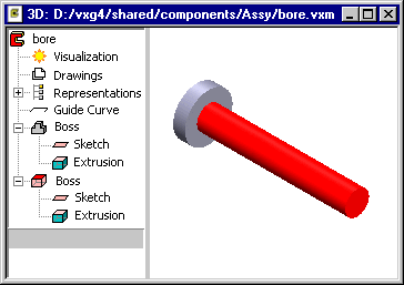
Figure 1: The completed tool. The red color of a feature symbol indicates that the feature is a machining feature. In a model the machining feature is also highlighted with a red color. - Add a tool to an assembly by selecting the context-sensitive function
 Add >
Add >  Component....
Figure 2: A tool has been added to the assembly. - Execute the machining feature by selecting the context-sensitive function
 Machining Features > Execute.
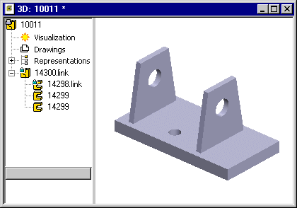
Figure 3: When the machining features of the model are executed, holes are machined in the sheet blanks.