
Adding Constraints in a Drawing
You can define geometric constraints for the elements in a 2D drawing of a building's drawing-model pair, or in another 2D drawing. The drawing can be made more accurate by adding constraints for defining the relation between the elements and dimensioning the elements. This results in a parametric floor plan or drawing.
 You can prevent the adding and solving of constraints by disabling the 2D Constraint Manager in the 2D drawing.

Constraint Types
Constraints are defined for the elements, lines and points in a drawing in order to enable its editing. Constraints defined for the elements include, for example, distance, radius and angle dimensions. These driving dimensions can be used to control the size, direction and position of the elements in relation to each other. In addition to driving dimensions, you can also add other geometric constraints to a drawing.
When an element has a geometric constraint, the element cannot be edited using its grip points. You must edit the geometry of a parametric drawing by editing the constraints.
Dimension constraints:
Other geometric constraints:
Using Functions to Define Constraints
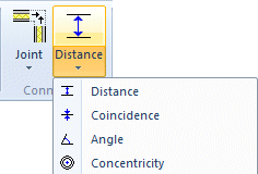
- You can add geometric constraints by selecting a constraint from the Modeling | Connection |
 Distance menu.
You can also add constraints from the Constraints group on the Drafting tab.
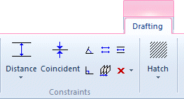
First select a function and then the elements between which you wish to add the constraint.
- You can later define a dimension added by the dimensioning function as a geometric constraint in the dimension properties. Change a regular dimension to a dimension constraint as follows:
- Select a dimension.
- Select
 Properties.
 - Select the check box Drives geometry in the dialog box.
- Confirm the data.
- If you wish all dimensioning functions to drive geometry, select the Dimensioning Tools Make Constraints checkbox in dimensioning settings.
Dimension Constraint Properties
When adding a dimension constraint, you can select dimension properties on the Properties tab. You can select properties in the same way as when adding or editing dimensions.
Unrealized Constraint
- Dimension constraints and other geometric constraints are highlighted in blue when the constraints are valid.
- Unrealized constraints are highlighted in red. For example, if too many constraints are defined for an element, the sketch is overdefined and the color of the constraints changes to red.
Editing Drawing Objects
You can edit drawing elements by editing the dimension constraints. You can select individual dimension constraints from the drawing and edit their dimension values. You cannot edit an element with a geometric constraint using its grip point.
Viewing the Constraints of a Drawing
The geometric constraints of a drawing are displayed as dimension constraints and graphical symbols. You can toggle their visibility with the F9 keyboard command.
You can view the constraints of a line element in the line property dialog box by selecting the element and then selecting the context-sensitive
Properties function. When you are adding a line, some geometric constraints are automatically created, when the 2D Automatic Constraints setting is enabled.