Adding Walls to a Parametric Building Model
Use parametric walls in the design. A binding is then created between the walls and height levels. Add the walls and other building components to their approximately correct locations and position them accurately at a later time using geometric constraints.
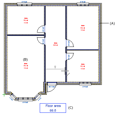
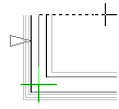
When you are adding walls, the wall center lines (A) in the floor plan indicate that the Associative Walls setting is enabled.
- Add the exterior walls. Note the following:
- Begin adding the wall from the drawing's origin.
- Add the walls in approximately their correct places. You can later define the accurate locations by adding geometric constraints between the walls.
- Click the wall corner points by going clockwise around the building.
The Position Fixed constraint is automatically created for the walls connected to the origin. When you later edit the floor plan by defining dimension constraints, the walls in question will always remain in place while the other walls move.
- Do either of the following:
- When you are adding an open wall chain, select the Confirm function.
- When you are adding a closed wall chain, click the last point to the start point. The wall chain is closed automatically.
- Select a floor structure. The program will automatically add it to its own drawing-model
pair based on the walls, while also adding the room label (B) and floor area (C). The
structure defined in the height levels is the default structure on the list.
 If you close the dialog box by
clicking Cancel, the automatic floor is not added and the setting
Automatic floor will be disabled from now on.
If you close the dialog box by
clicking Cancel, the automatic floor is not added and the setting
Automatic floor will be disabled from now on. - Add the interior walls. Use the
 Room-creating wall function in the auxiliary menu. The program
will automatically create a new room in the floor plan based on the added wall. Joint
constraints are automatically created between the walls.
Room-creating wall function in the auxiliary menu. The program
will automatically create a new room in the floor plan based on the added wall. Joint
constraints are automatically created between the walls.
- Add windows, doors and other building components as usual.

When you have created a floor plan, you can define geometric constraints to define the
relations between building components and dimension them. You can view the wall constraints in
the drawing or model by selecting the  Constraints function from the context-sensitive menu.
 Note
Note
- The wall center line is on layer 218, Construction Line.
- When Automatic Floors and Automatic Rooms are enabled, you cannot delete floors or rooms. The program will automatically generate them every time you edit or update the floor plan.
- When you add windows and doors using the
 Enter Distance from Point auxiliary function, a dimension
constraint is automatically created. The constraint is added on the layer 92 Dimension
Constraints.
Enter Distance from Point auxiliary function, a dimension
constraint is automatically created. The constraint is added on the layer 92 Dimension
Constraints. - When adding walls, the free ends of the walls are presented in the floor plan with the
following symbol: