
Create A Linear Pattern for the Specified Interval
You can click the length and direction of the pattern if you enter only the number of parts as the pattern data. The members of the pattern are placed equally at this length.
The instructions describe the creation of the pattern with the context-sensitive function:
- Select the part from which you wish to create a pattern from the assembly.
- Select the context-sensitive function
 Pattern.
 - Select Linear in the dialog box of the assembly pattern.
- Confirm the location: New pattern.
- Enter only the Number of parts.
- Do not enter length or interval values.
- Select OK.
- The program opens an auxiliary window and asks to click the points.
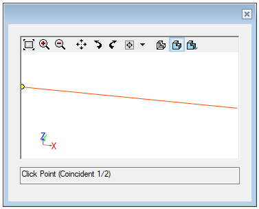
- The program opens an auxiliary window and asks to click the points.
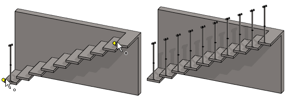
- For a linear pattern in one direction, click two points between which the pattern is created. For a linear pattern in two directions, click three points that define the pattern's X-axis direction and Y-axis plane.
- The first point defines the starting point of the control part.
- The second point defines the direction of the X-axis (red).
- The third point (in a two-direction linear pattern) determines the direction of the Y-axis (green).
- The program adds a coincidence constraint between the endpoints of the control part and the indicated geometry.
Note:
- You can edit the properties of a linear pattern by selecting the pattern from the assembly tree and then selecting the Edit function.
- When you add the pattern using the New Pattern selection, the program will add the
 PATTERNXY control part to the pattern. After adding the pattern you can edit the direction and relative positions of the components in the 3D sketch of the control part.