
Edit a Part in an Assembly with Another Part
General
The  Boolean function is about modeling a part in an assembly using the geometry of other parts in the assembly.
Boolean function is about modeling a part in an assembly using the geometry of other parts in the assembly. - This method is suited in the design of molds and/or stressed-skin structures.
- The part that modifies the part acts as an external reference.
Other parts can be used to:
- Add geometry to a part.
- Remove geometry from a part.
- Create geometry for a part from the common geometry volume of the part itself and another part (Boolean section).
- Remove tool geometry from a part that is in another part.
The Boolean function edits the (link) part of the assembly.
Boolean function edits the (link) part of the assembly.- The step Boolean operation is added to the history of the part
- If you want to see which part has been used to modify the part, momentarily move the cursor over the part's history step Boolean operation. The tip text that opens tells you the part and the assembly where the modification has been performed.
- The Thread symbol feature moves from the machining part to the machined part in the operation when the option Subtract with tool is selected. At the same time, the type of the thread changes to the opposite, i.e. machining with an external thread creates an internal thread and vice versa.
Edit a Part or Parts with Another Part or Parts
This describes the functionality in an assembly when no parts are selected.
- Select the context-sensitive function Boolean.
- The program opens the dialog box Boolean Operation.
- Select the operation
- Subtract
- Unite
- Intersect
- Subtract with tool
- Select
 Only biggest volume stays, if you want, for example, the largest individual volume of the part to be connected to be connected to the part. See the examples below
 - Enter the Offset if you want a gap to be added between the part to be edited and the tool part.
- Under Parts, select the part or parts that you want to modify with other parts.
- Click the Add button.
- Select the part or parts.
- Confirm the selection. (Confirm = V key, middle mouse button or the context-sensitive
 OK.)
OK.)
- Under Tool Parts, select the part or parts that you want to use to modify.
- Click the Add button.
- Select the part or parts.
- Confirm the selection. (Confirm = V key, middle mouse button or the context-sensitive OK.)
- If necessary, you can add, change or delete both the parts to be modified and the tool parts with the buttons:
- Insert
- Change
- Delete
- Select OK.
Note: You can also find the function
When you first select the part
- In this case, the selected part works as a modifying part and can be found in the list Tool Parts.
- You need to select the part or parts to be modified.
When you edit a part in an assembly
- The part is automatically the part to be modified.
- In this case, you can only select the tool parts.
Note: If the parts used in the Boolean operation have changed, you can solve the assembly parts dependent on these either part-specifically or all parts at once with the context-sensitive function  Solve.
Solve.Delete the Boolean Feature from a Part
- Select the part.
- Select the following contextual function: Edit.
- In the feature tree, select the history step: Boolean operation.
- Select the context-sensitive function Delete Feature.
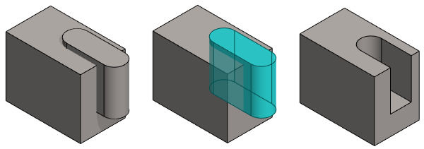
Example 1: Subtract
- The geometry of another (blue) part has been removed from the prism.
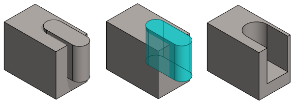
Example 2: Subtract with offset
- The geometry of another (blue) part has been removed from the prism.
- A positive offset value has been used.
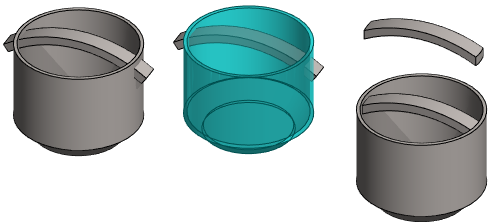
Example 3: Subtract, only biggest volume stays
- The cup (blue part) and the small volumes outside the cup has been removed from the handle.
- Selected: Only biggest volume stays
Example 4: Intersect
- Only the volume that is common to the part to be modified and the tool part (blue) is left in the part to be modified.

Example 5: Subtract with tool
- This functionality should be used if you want to machine the link part with the tool of another part.
- In the function
 Machining Features > Execute the original link part is not modified. Execute Machining Features
 - The tool geometry contained in the other (blue) part has been removed from the round disc.

Other examples
- Leaving a welding groove between the parts: Edit Parts with Other Parts - Welding Groove
- Pipe through a loose hole: Edit Parts with Other Parts - Pipe Lead-throughs