
Edit Parts with Other Parts - Welding Groove
You can fit parts together in an assembly.
For example, a standard welding groove can be added between sheet metal parts with the Boolean function.
An example of editing with parts.
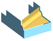
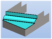
- The starting point is an assembly model, which includes the following:
- Jig part
- Finished plate section modeled with the Jig.
- Jig part
- Select the context-sensitive function New Part, and name the part.
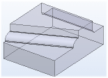
- Select the context-sensitive function Copy Surface.
- Select the Tangential Shelling search.

- Select the face.
- Select Confirm.
- Define the properties in the Copying a Face dialog box.
 In is selected.
- Select
 To Volume.
- Select OK.
- Define the properties in the Surface Chain Data dialog box.
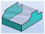
- Change to Sheet Metal Part is selected.
- Define the sheet thickness.
- Select the material by clicking the Select button.
- Select OK.
- Exit the part modeling mode. Select Confirm.
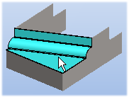
You can hide the Jig part to see the new part in more detail. Select the part and press the H key.
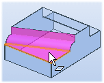
- When nothing is selected, select the context-sensitive function Boolean.
- Define in the Boolean dialog box.
- Operation Subtract.
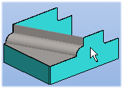
- Offset Value - In the example, the offset value defines the welding groove. Enter the value. The welding groove is a smaller volume than the plate part.
- Select Only the Biggest Volume Stays.
- Editable Parts - Select the part to be edited. Click the Add button and select a part from the model. Select Confirm.
- Tool Parts - Select the the tool part. Click the Add button and select a part from the model. Preview by clicking the Apply button. Select Confirm.
- Select OK.
