
Extrude as a Composite Sheet
Composite Sheets
You can extrude the sketch perpendicular as the composite sheet, which can be a single, two or three-layer composite sheet.
You can define the material and thickness of the top, middle and bottom of a composite plate.
When using the function as the first feature on the part model, the part is defined as a composite sheet part.
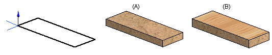
A sketch is drawn on the Horizontal(XY) plane. The sketch is extruded as a single-layer (A) or three-layer composite sheet (B).
 Sketch a closed polyline on the horizontal(XY) plane, so that the surface materials settle on the bottom and top of the plate. The longitudinal direction of a composite plate (plate direction) is determined in such a way that if you draw the first sketch of the composite plate on the horizontal(XY) plane, the X direction of the sketch is the longitudinal direction (plate direction) and the Y direction is the latitudinal direction.
The direction of the composite plate affects the sheet data collected in the parts list. The preform dimensions (Preform) and area (Quantity) are calculated automatically in the material data according to the overall dimensions, taking the direction of the plate into consideration, unit sq.m and with an accuracy to within 0.01 sq.m.
Create an extrude based on the sketch. Define the extrude properties in the dialog box.
- Select the operation.
- Add material - Select
 Add and
  Composite Sheet.
 - Delete material - Select
 Delete, and Composite Sheet.
 - You can extrude the sketch to

 Both Directions.
- Add material - Select
- You can select the material (item) of the top, middle or bottom from the list by first selecting the appropriate checkbox for the plate and clicking the Select button.
 Composite Sheet Properties Select an Item from a List
- The material selection will also determine the plate thickness. You can edit the material thickness value, if required.
- If you select the item in the Plate Code field, the plate code specify the whole structure of the composite sheet: top, core and bottom material, and the material thicknesses.
- Click OK.
- You can change the longitudinal direction (plate direction) and material direction of a composite sheet by selecting the part and the context-sensitive function Visualization> Plate Direction. The latitudinal and thickness directions of the plate are defined at the same time. The direction of the plate affects the sheet data collected in the parts list.
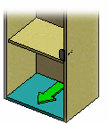
- If you select a composite part in a model, the lengthways direction (sheet direction) of the sheet is indicated with an arrow. You can also see the sheet direction in parts selected in an assembly model.
- To edit composite sheet data, select the feature to edit or select the part and the context-sensitive function Properties. In the part properties, you can also define the archives data as well as the label and material data of the part.
- You can flip the direction of the extrusion of a composite sheet by selecting the feature for editing. When you are creating a composite sheet feature, you can reverse the extrusion direction in the sketching mode by clicking the Flip button in the Composite Sheet Properties dialog box.