Loft
Prerequisites for the function
- The part model has at least two surfaces between which the loft is created.
- The part model has the necessary guide curve features if you want to control the generated shape with the guide curves.
- The guide curves are modeled so that they coincide with the edge curves of the cross-sections.

Add a loft with the ribbon bar function
- Select an adding or removing loft on the
 tab in the Lofting group
- An adding loft
 Boss.
Boss. - A removing loft
 Cut
Cut
- An adding loft
- Select two or several surfaces between the material is added.
- Confirm the selection of faces with the Confirm function. (Confirm = V key, middle mouse button or the context-sensitive
 OK.)
OK.)- The Loft dialog box opens.
- Edit the loft data in the dialog box.
 Loft Feature Data
- Define the tangency type.
- Tangency factors are available if you have selected surfaces of a part.
- If necessary, you can add or remove tangential lines or cross-sections.
- You can define the twist type.
- Select OK.
Add a loft with the context-sensitive function
- Select two or more cross-sections or surfaces.
- Hold down the Ctrl key when you select the second, third etc. surface.
- Select the context-sensitive adding or removing loft
 Loft > Boss.
 Loft > Cutout.
- See steps 4...5 above.
Example: Loft between two planar surfaces

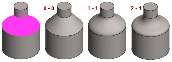
- Left: Two surfaces selected from the part, between which lofting is applied.
- Second from the left: No tangency or tangency factors are zero.
- Third from the left: Tangency to both end surfaces with a factor of 1.
- On the right. Tangency to one end surface with a factor of 2 and to the other 1.
Example 2
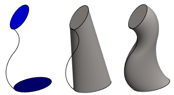
Loft between a cylindrical face of a volume and a planar loft section, with tangency on the guide curve.

Example 3
Loft between a cylindrical face of a volume and a planar loft section, with tangency on virtual guide curves.

Example 4
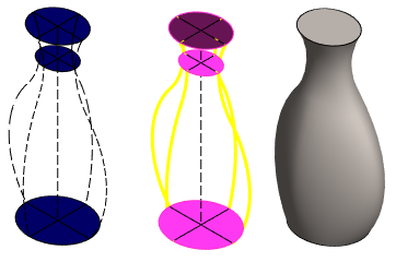
Loft between two cross-sections.

- Middle: No tangency.
- On the right: tangency to guide curves.
Example 5
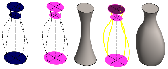
Loft between several loft section faces, with tangency on the guide curve.

