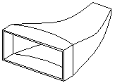
Example: Loft with a Non-planar Surface and Guide Curve
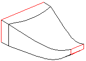
Lofts can be created using two or more loft sections on one or more guide curves. The cross section can be in plane or not.
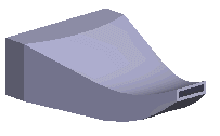
You can create a loft as follows:
- Sketch the cylinder face. Draw a construction line on a sketch for positioning a guide curve.
- Sketch the cross section on plane. Draw a construction line on a sketch for positioning a guide curve.
- Sketch the guide curve. Select the starting and ending points of the guide curve on construction line points.
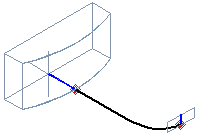
- Select cross sections.
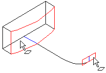
- Select the function
 Loft> Boss.
 - Control the loft using the selections in the dialog box as follows:
- Select tangency to Virtual guide curves. The program prompts you to select the lines of the guide curve.
- Select the elements one by one, and select the function Confirm.
- Select OK.
- Select both end surfaces from the volume.
- Select the context-sensitive function
 Shell.
 - Select In or Out.
- Define the wall thickness to the Value field.
- Select OK.
