
Control Lofting by Twist
General
- Twist is caused by differences in the shape of the loft section faces. The program attempts to automatically delete twist from the loft.
- As a general rule, it is not necessary to interfere with the twist if the cross-sections are modeled in such a way that they have the same number of lines and the lines and arcs of the cross-sections alternate in the same order.
- Note that this is why it is not advisable to loft a rectangle and a circle.
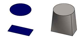
- Instead, it is advisable to loft two rectangles rounded around their corners, one of which has a shape close to the rectangle and the other close to a circle.

- Note that this is why it is not advisable to loft a rectangle and a circle.
You can affect twist using location points as follows:
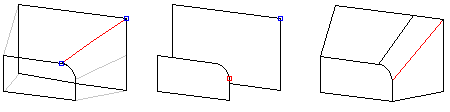
- Move a location point.
The location points are automatically placed at the corner points of a loft section face that has no tangential edge lines. On other faces the location point is positioned, for example, at the end point of a curved edge line. Only one of these location points is displayed per face. You can move a location point by selecting a new place for it.
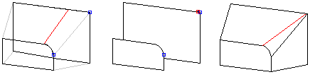
- Add a location point.
You can control twist by adding a location point near the corner of a rectangular face, making the loft to look as desired. The loft section face location points have counterpoints.
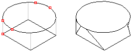
Twist can be generated using location points. Add three location points to a circular loft section to correspond with the location points in the corners of a rectangular face.
Moving a location point
You can define the position of a location point on a line as a relative value in relation to the length of the line. The relative position can have values 0-1. Relative position 0 means the start point of the line, 0.5 is the middle point of the line, and 1 is the end point of the line.
- Select a loft for editing.
- Select the loft data in the dialog box in the section Rotatation, and select By the position points.
- Select the desired Point from the list. The selected point is highlighted in the model.
- Click the Change button.
- Select a new position for the point on the edge line of the face.
- Enter the relative position on the line for the point.
Adding an Alignment Point
- Select a loft for editing.
- Select the loft data in the dialog box in the section Rotatation, and select By the position points.
- Move the cursor to an empty line in the list.
- Click the Add button.
- Select a position for the point on the edge line of the face.
- Select Confirm.
Deleting a location point
Location points that have been automatically added by the program cannot be deleted from the model, but you can move them.
- Select a loft for editing.
- Select the loft data in the dialog box in the section Rotatation, and select By the position points.
- Select one point at a time from the list.
- Click the Delete button.