
Loft Feature Data
Define the data of the feature:
- Select the tangency method and select any associated guide curves.
- Enter the tangency factors if you selected the tangency method To end faces.
- Add, delete or change surfaces or cross sections involved in the lofting, if necessary.
- If necessary, control the lofting of surfaces that deviate from each other's shape with rotation points.
- If necessary, change the adding loft to the removing loft or vice versa.
- If necessary, make the loft in a closed shape.
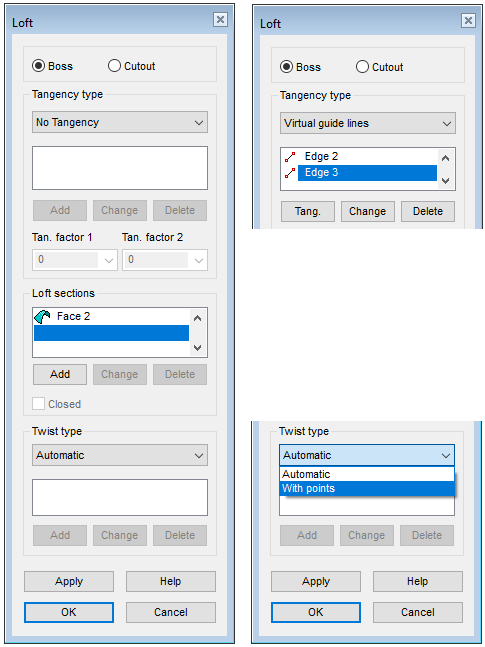
Dialog Box Options
- Boss or Cutout
- Select an adding or deleting loft.
- If the part model does not yet have volume geometry, then the only option is Boss.
- Tangency type
- Select the desired tangency type:
- No tangency
- The loft is created without tangency to the guide curves or end surfaces.
-
Guide lines
- The loft is tangential to the selected guide curves.
- The guide curve must cut (be tangential to) the edge curve of the cross section.
- Selecting a tangential guide curve consisting of several lines becomes easier if you use the auxiliary menu option
 .
. - Stop selecting guide curves by selecting Confirm (Confirm = V key, middle mouse button or the context-sensitive function
 OK).
OK). - See: Use Guide Curves in Lofting
-
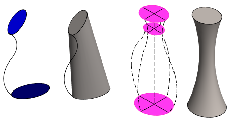
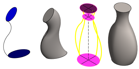
Virtual guide lines
- In addition to the selected guide curves, the program adds the virtual guide curves it needs, so this option gives a better result in some cases than tangential to the guide curves.
Example of the difference between a guide curve and a virtual guide curve:
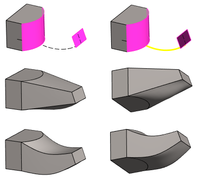
- In the top row, on the left, the surfaces on the basis of which the loft is made, and on the right, the selected guide curve.
- In the middle row, tangency to Guide lines.
- In the bottom row, tangency to Virtual guide lines.
- To end faces
- This option is available if you select end surfaces from a part instead of cross sections.
- Tangency factor 1 and 2
- Define the value of the tangency factor separately for both end faces. You can define the factor if you have selected the tangency type To end faces.
- Define the factor of the end surface you selected first in the field Tan. factor 1
- Define the factor of the end surface you selected second in the field Tan. factor 2.
- When the factor value is 0, the edge lines of the loft faces are not tangent to the end face at all.
- Recommendation: Try the small factors first. Factors 3 could not be used for the part in the example below. Factor 2.8 was fine.
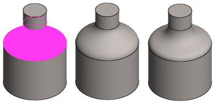
Examples of end surface tangency factors.

- Cross sections
- Defines the cross sections based on which the loft feature is modeled. You must select at least two loft section faces for lofting. They can also be the end faces of a volume.
- If you are creating a loft based on more than two cross sections, note the correct selection order.
- The selected elements are displayed on the list in numerical order.
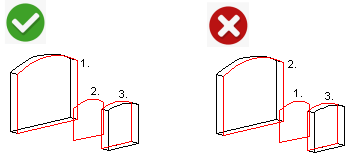
- Adding, changing, deleting loft section faces and guide curve lines
- View, change or delete selected elements in the loft with the buttons.
- Select an element from the list.
- Click the required button: Add, Delete or Change..
- Add a face to the loft:
- Select Face N from the list, in front of which you will add a new cross-sectional surface.
- Select the context-sensitive function Add.
- Select the face.

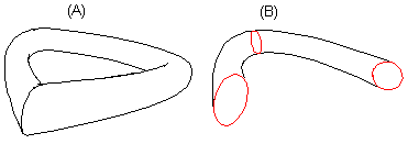
- Closed
- Defines the loft as a closed chain of faces (A), when this checkbox is selected. This function can be selected if three loft sections have been selected at least. This will automatically loft the space between the first and last loft sections. If the checkbox is empty, lofting is performed only between the selected loft section faces (B).
- Rotation
- Defines either deletion of automatic torsion or adds torsion using location points.
- View, change or delete loft location points with the buttons, see
 Twist in Lofting.
 - Apply
- Preview by clicking the Apply button. This will show you how the model would look if you confirmed the feature data by clicking OK. If necessary, you can still edit the feature data.