
Add a Profile Joint Component
General
- Joint components can be components added to the joints between profiles, which can include plates, screws, nuts and washers and which can also drill the holes needed for the joint in the profiles.
- Joint components can also be flanges added to the ends of the profile.
- The components are parametric and their dimensions can be modified using dimension tables.
- The components are connected to the selected profiles with automatically added constraints.
- Different joint components behave in slightly different ways, some ask for direction, some do not. See related examples, links to examples at the end of the instructions.
- The profile joint components have been implemented as so-called adaptive assembly components, where the assembly and sketch constraints are named in such a way that the program can automatically recognize the elements of the desired constraints to be reconnected from the profiles selected for joint.
- The named constraints of the joint component also define whether the component connects two profiles to each other or whether the component is connected only to the end of one profile.
- Joint components already added to the assembly can be edited using the dimension table.
- The parts list collects information about the screws, nuts, washers and reinforcement plates of the joint components.
- To remove a joint component, select it in the feature tree and select the context-sensitive function
 Delete.
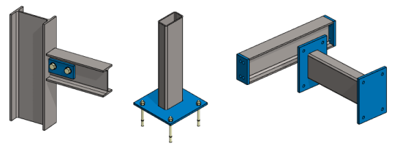
Add a Profile Joint Component
- Select Assembly |
 Add >
Add >  Profile Joint or
- select the context-sensitive function
 Add > Profile Joint.
 - The program opens the Profile Joints library, which is divided into folders.
- select the context-sensitive function
- Select a folder.
- Fin plates. (Includes components ProfJoint03*)
- Splice plates. (ProfJoint06*)
- Base plates. (ProfJoint01*)
- End plates. (ProfJoint02*)
- Face plates. (ProfJoint04*)
- Tools
- Diagonal bracing (ProfJoint07*).
- Passing. (ProfJoint05*)
- Select the joint component
- Double-click the component or
- select the component and drag it a small distance and release the cursor or
- select the component and select the context-sensitive function
 Add.
Add.
- Select the the target profile, to which the joint component is added.
- Select the profile to be connected if the joint component asks for it.
- If necessary, click the direction of the joint component.
- It is recommended to click the direction on the surface of the profile web.
- The program opens the dialog box Dimension Table.
- Enter the dimensions of the joint component.
- In some cases, some of the variables are ignored, even if you enter a new value for them.
- If necessary, select a different size for the screw, nut or washer component.
- Select the component from the Components section of the Dimension Table dialog box.
- Click the preset button
 in the New Size field.
- The program opens the list of screw size options.
- Select another size from the list.
- Select Apply to see in the model what the joint component would look like with these dimensions.
- The option
 Preview in the Dimension table dialog box is not available.
- The option
- Click OK to accept the dimensions entered.
- Continue adding similar joint components, repeating steps 3...6.
- Stop adding joint components
- Select another function or
- Press the middle mouse button or
- Press the V key or
- Press the Esc key or
- select the context-sensitive function
 OK.
OK.
Examples
See the examples