
Add a SmartSnap Component to an Assembly
Library
SmartSnap components are added to assemblies as local parts.
- A SmartSnap component can be a part or an assembly. It is also called an adaptive component.
- When you add a SmartSnap component to an assembly, you are also positioning the component in the assembly with geometric constraints.
- When SmartSnap components are added, assembly constraints left free are taken into consideration. You can position the component in approximately the right location by dragging, and use constraints to define the final positioning.
- Positioned SmartSnap components have external references to the surrounding assembly geometry. If you edit the assembly geometry, the SmartSnap component will adapt accordingly.
You can find the program's sample components in the component library folder System/SmartSnap.
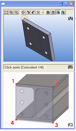
As an example, the end plate of an I beam (part).

Add a SmartSnap component to an assembly as follows:
|
 |


Note:
- If you edit the geometry of the assembly, select the
 Solve function. This function will solve the parts with external references in the assembly model, such as the SmartSnap components. Subassemblies inserted in to the assembly as links are to be solved only if the subassembly has the
  Solved as Subassembly property.
 - Insufficient constraint definition. If a SmartSnap component added to an assembly has insufficient constraint definitions, these will be displayed in the feature tree of the part in the sketching mode as follows:

A matching element connected to the Coincident constraint (point, line or face) is missing from the assembly geometry.