
Add a Parallel Constraint
General
- The parallelism of the planar surfaces means that they or their extensions do not intersect.
- If you add a distance constraint between planar surfaces, that also sets the surfaces parallel.
- Lines (segments) are parallel if they are in the same plane and do not intersect.
- The parallelism of a planar surface and a line means that the surface normal and the line are parallel, i.e. the line intersects the surface in a position perpendicular to the surface.
Add a parallel constraint between parts
- Select Assembly | Constraints |
 Add parallel constraint.
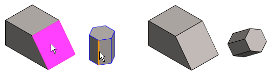
 - Select the appropriate face or line on the first part.
- Select the appropriate face or line on the second part.
- The parts will be positioned in accordance with the constraint.
- Continue repeating steps 1 ... 3 until all the desired constraints have been added.
- Stop adding parallel constraints:
- Select another function.
- Press the Esc key.
- Press the V key (Confirm).
- Select the context-sensitive function
 OK.
OK. - Click the middle mouse button.
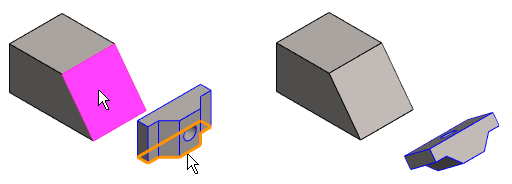
Example: Parallelism between a surface and a line
- The parallelism is between the surface normal (purple in the figure) and the line.
Note:
- You can also use this function by first selecting the two parts, and then
- The ribbon bar function Add parallel constraint or
- The context-sensitive function Constraints > Parallel.
- Select the second part Ctrl+left mouse button.
- The ribbon bar function
- You can define a constraint as configuration-specific by selecting the constraint and then selecting the context-sensitive menu function Edit.
- Zoom the part view by the Z key to select an element. Zoom all by pressing the A key.
- Move a part by moving the cursor onto a part, then moving the mouse while holding down the left mouse button.
