
Add a Perpendicular Constraint
General
- The surfaces are perpendicular to each other when they intersect at an angle of 90 degrees.
- The perpendicularity of the planar surface and the line means that the surface normal and the line are at an angle of 90 degrees to each other, i.e. the line or its extension does not intersect the plane surface.

Add a perpendicular constraint between parts:
- Select Assembly | Constraints |
 Add perpendicular constraint.
 - Select the appropriate face or line on the first part.
- Select the appropriate face or line on the second part. The parts will be positioned in accordance with the constraint.
- Continue repeating steps 1 ... 3 until all the desired constraints have been added.
- Stop adding perpendicular constraints:
- Select another function.
- Press the Esc key.
- Press the V key (Confirm).
- Select the context-sensitive function
 OK.
OK. - Click the middle mouse button.
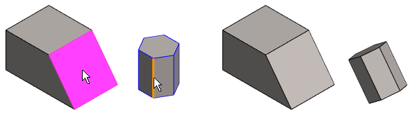
Example: perpendicularity between a planar surface and a line
- The perpendicularity is between the surface normal (purple in the figure) and the line.
Note:
- You can also use this function by first selecting the two parts, and then
- The ribbon bar function Add perpendicular constraint or
- The context-sensitive function Constraints > Perpendicular.
- Select the second part Ctrl+left mouse button.
- The ribbon bar function
- You can define a constraint as configuration-specific by selecting the constraint and then selecting the context-sensitive menu function Edit.
- Zoom the part view by the Z key to select an element. Zoom all by pressing the A key.
- Move a part by moving the cursor onto a part, then moving the mouse while holding down the left mouse button.
