
Add a Symmetry Constraint
General
- Symmetry is always defined with respect to a planar surface.
- The elements that are desired to be symmetric are clicked first, followed by the symmetry plane.
Add a symmetry constraint between parts
- Select Assembly | Constraints |
 Add symmetry constraint.
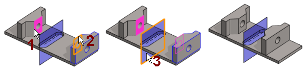
 - Select a face, line, or a point from the first part.
- Select a face, line, or a point the second part.
- Select the symmetry plane from the third part.
- The symmetry plane can also be an auxiliary plane.
- The parts will be positioned in accordance with the constraint.
- Continue repeating steps 1 ... 4 until all the desired constraints have been added.
- Stop adding symmetry constraints:
- Select another function.
- Press the Esc key.
- Press the V key (Confirm).
- Select the context-sensitive function
 OK.
OK. - Click the middle mouse button.
Note:
- You can also use this function by first selecting the two parts, and then
- The ribbon bar function Add symmetry constraint or
- The context-sensitive function Constraints > Symmetry.
- Select the second part Ctrl+left mouse button.
- The ribbon bar function
- You can define a constraint as configuration-specific by selecting the constraint and then selecting the context-sensitive menu function Edit.
- Zoom the part view by the Z key to select an element. Zoom all by pressing the A key.
- Move a part by moving the cursor onto a part, then moving the mouse while holding down the left mouse button.
