
Define the Surface Properties of a Surface Model
About surface properties
- The surface has a direction which in a "normal" part is always outwards.
- The surface has an identifier (id) given by the program and, if necessary, the user can give the surface a name.
- The name of the surface can be used, for example, in product automation systems when adding constraints.
- The surfaces are so-called semi-transparent:
- The outside of the surface is visible.
- The inside is invisible, that is, you can see through the surface as if it did not exist.
- In the settings, you can choose whether the surfaces are displayed as semi-transparent or whether both sides of the surface are always displayed.
Surface direction and side
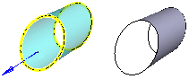
- When adding a surface, you also select the direction of the surface normal.
- The surface normal is illustrated with a blue arrow and it points to the outside of the surface.
- You can reverse the normal direction when you add a surface.
- Later, you can change the direction of the surface with the Flip direction function Flip a Face's Direction.
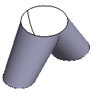
- The outside of the surface is visible and the inside is hidden.
As the default, the outsides of the surfaces are displayed in a part.
The sides of the surface is important when a volume is created from the surface or its line of surfaces.
- The surfaces must have the same direction.
- If necessary, you can flip the surface: Flip a Face's Direction
Surface visibility
By default, surfaces are only visible from the outside. When modeling a part using surfaces, it is a good idea to make both sides of the surfaces visible. Set both sides visible.
- File >
 User Preferences > Drawings, Models > View tab, Model group >
  Show both surface sides always.
 In order not to slow down the processing of a large assembly model, it is a good idea to turn off the Show both surface sides always setting when surface modeling is finished.
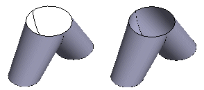
- On the left, the default, i.e. only the outside of the surfaces is visible, and on the right, when both sides of the surface are visible.
Name the surface
- You can use the name of the surface in the Product Automation System.
- Select the face.
- Select the context-sensitive function
 Properties.
- The program opens the dialog box Name?.
- Enter a name for the surface.
- OK.
Note: Move the cursor over the surface and stop it for a moment. In this case, the program displays a tip text whose content is
- Name (if the surface is given a name).
- Part name.
- Shape. For example, Plane, Sphere, Cylinder, Spline.
- Id (i.e. the "address" of the surface used by the program).